Dodge Journey: Reinforcement, bumper, front
REMOVAL

Fig. 23: Front Bumper Reinforcement
1. Remove the front fascia. See Removal .
2. Support bumper reinforcement (3) on a suitable lifting device.
3. Mark the position of the bolts (1) on frame rail to aid in installation.
4. Remove the smaller bolts (2) attaching bumper reinforcement (3) to frame rail.
5. Remove the larger bolts (1) attaching bumper reinforcement (3) to frame rail.
6. Remove bumper reinforcement (3) from vehicle.
INSTALLATION
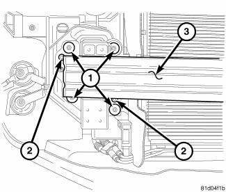
Fig. 24: Front Bumper Reinforcement
1. Position the bumper reinforcement (3) on vehicle.
NOTE: Use marks made previously to properly position bumper reinforcement
2. Install the larger bolts (1) attaching bumper reinforcement (3) to frame rail. Tighten bolts (1) to 28 N.m (250 in. lbs.).
3. Install the smaller bolts (2) attaching bumper reinforcement (3) to frame rail.
4. Install front fascia.
 Fascia, rear
REMOVAL
Fig. 15: Push Pins
1. Open the hatch.
2. Remove the 6 pushpins (1) securing the fascia (2).
Fig. 16: Rivets
3. Remove the rivets (2) and the Torx screw (3) around the wheel well for ...
 Reinforcement, bumper, rear
REMOVAL
Fig. 25: Rear Bumper Reinforcement
1. Remove rear fascia. See Removal .
2. Support bumper reinforcement (1) on a suitable lifting device.
3. Mark position of bolts (2) on frame rail ...
See also:
Description, Operation
DESCRIPTION
Fig. 221: Condenser Description
NOTE: A/C condenser with automatic transmission cooler shown. A/C
Condenser
without cooler similar.
The A/C condenser (1) is located in the f ...
Description, Operation, Diagnosis and Testing
DESCRIPTION
Fig. 1: Accessory Switch Bank Module
Vehicles with the heated seat option can be visually identified by the two
heated seat switches (1) located in the
center stack of the instrumen ...
Camshaft, engine
DESCRIPTION
Fig. 108: Camshaft & Valvetrain Components
- CAMSHAFT BEARING CAP - INTAKE
- CAMSHAFT BEARING CAP - EXHAUST
- CAMSHAFT - EXHAUST
- ROCKER ARM
- HYDRAULIC LIFTER
- CYLI ...
