Dodge Journey: Reinforcement, bumper, rear
REMOVAL
Fig. 25: Rear Bumper Reinforcement
1. Remove rear fascia. See Removal .
2. Support bumper reinforcement (1) on a suitable lifting device.
3. Mark position of bolts (2) on frame rail to aid in installation.
4. Remove bolts (2) attaching rear bumper reinforcement (1) to frame rail.
5. Remove bumper reinforcement (1) from vehicle.
INSTALLATION

Fig. 26: Rear Bumper Reinforcement
1. Position rear bumper reinforcement (1) on vehicle.
2. Install bolts (2) attaching bumper reinforcement to frame rail. Use marks made previously to properly position bumper reinforcement.
3. Tighten bolts (2) to 28 N.m (250 in. lbs.).
4. Install rear fascia.
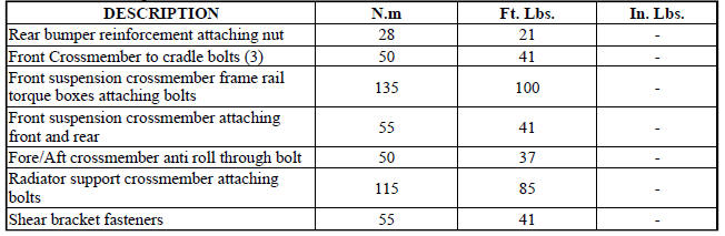
SPECIFICATIONS
FASTENER TORQUE
 Reinforcement, bumper, front
REMOVAL
Fig. 23: Front Bumper Reinforcement
1. Remove the front fascia. See Removal .
2. Support bumper reinforcement (3) on a suitable lifting device.
3. Mark the position of the bolts (1) ...
 Frame
Frame
SPECIFICATIONS
FRAME DIMENSIONS
Frame dimensions are listed in metric scale. All dimensions are from center
to center of Principal Locating
Point (PLP), or from center to center of PLP and fasten ...
See also:
Ring(s), piston
Standard Procedure
PISTON RING FITTING
Fig. 200: CHECK GAP ON PISTON RINGS
- FEELER GAUGE
1. Wipe cylinder bore clean. Insert ring and push down with piston to ensure
it is square in bore ...
Description, Operation
DESCRIPTION
Fig. 418: Identifying Ignition Key/Switch Positions
- LOCK
- ACC
- ON
- START
The Brake Transmission Shifter/Ignition Interlock (BTSI) is a solenoid
operated system that ...
Removal, Installation
REMOVAL
WARNING: Refer to the applicable warnings and cautions for this
system before
performing the following operation. Failure to follow the warnings and
cautions may result in po ...
