Dodge Journey: Removal, Installation
REMOVAL
WARNING: Disable the airbag system before attempting any steering wheel, steering column, or instrument panel component diagnosis or service. Disconnect and isolate the negative battery (ground) cable, then wait two minutes for the airbag system capacitor to discharge before performing further diagnosis or service. This is the only sure way to disable the airbag system. Failure to take the proper precautions may result in accidental airbag deployment and possible serious or fatal injury.
NOTE: The single zone heating-A/C system is equipped with a single blend door actuator. The dual zone system has two blend door actuators, one for the driver side blend-air door and one for the passenger side blend-air door.
NOTE: LHD model shown in illustrations. RHD model similar.
SINGLE ZONE/DUAL ZONE LEFT SIDE

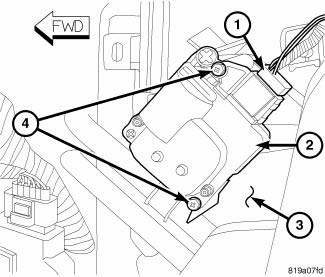
Fig. 8: Blend Door Actuator Removal/Installation
1. Disconnect and isolate the negative battery cable.
2. On RHD models, if equipped, remove the silencer from underneath the passenger side of the instrument panel.
3. On RHD models, remove the glove box bin.
4. Disconnect the wire harness connector (1) from the blend door actuator (2) located on the left side of the HVAC air distribution housing (3).
5. Remove the two screws (4) that secure the blend door actuator to the air distribution housing and remove the actuator.
DUAL ZONE RIGHT SIDE

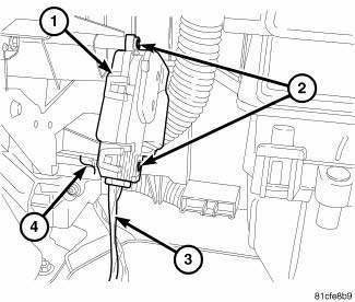
Fig. 9: Blend Door Actuator Dual Zone Passenger
1. Disconnect and isolate the negative battery cable.
2. On LHD models, if equipped, remove the silencer from underneath the passenger side of the instrument panel.
3. On LHD models, remove the glove box bin.
4. Remove the front floor distribution duct from the right side of the air distribution housing.
5. Remove the screws (2) that secure the blend door actuator (1) to the right side of the air distribution housing (4) and remove the actuator from the housing.
6. Disconnect the wire harness connector (3) from the blend door actuator and remove the actuator from the vehicle.
INSTALLATION
NOTE: The single zone heating-A/C system is equipped with a single blend door actuator. The dual zone system has two blend door actuators, one for the driver side blend-air door and one for the passenger side blend-air door.
NOTE: LHD model shown in illustrations. RHD model similar.
SINGLE ZONE/DUAL ZONE LEFT SIDE

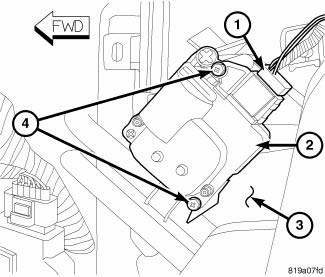
Fig. 10: Blend Door Actuator Removal/Installation
1. Position the blend door actuator (2) onto the left side of the HVAC air distribution housing (3). If necessary, rotate the actuator slightly to align the splines on the actuator output shaft with those in the blend air door linkage.
2. Install the two screws (4) that secure the blend door actuator to the air distribution housing. Tighten the screws to 2 N.m (17 in. lbs.).
3. Connect the wire harness connector (1) to the blend door actuator.
4. On RHD models, install the glove box bin.
5. On RHD models, if equipped, install the silencer underneath the instrument panel.
6. Reconnect the negative battery cable.
7. Initiate the Actuator Calibration function using a scan tool.
DUAL ZONE RIGHT SIDE

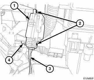
Fig. 11: Blend Door Actuator Dual Zone Passenger
1. Position the blend door actuator (1) to the right side of the HVAC air distribution housing (4) and connect the wire harness connector (3) to the actuator.
2. Install the blend door actuator onto the air distribution housing. If necessary, rotate the actuator slightly to align the splines on the actuator with the blend door linkage.
3. Install the two screws (2) that secure the blend door actuator to the air distribution housing. Tighten the screws to 1.2 N.m (10 in. lbs.).
4. Install the right front floor distribution duct onto the air distribution housing.
5. On LHD models, install the glove box bin.
6. On LHD models, if equipped, install the silencer underneath the instrument panel.
7. Reconnect the negative battery cable.
8. Initiate the Actuator Calibration function using a scan tool.
 Description, Operation
DESCRIPTION
Fig. 7: Blend Door Actuators
The blend door actuators (1) for the front heating-A/C system are reversible,
12-volt direct current (DC) servo
motors. Models with the front single zon ...
 Actuator, mode door, front
DESCRIPTION
Fig. 12: Blend Door Actuators
The mode door actuator (1) for the heating-A/C system is a reversible,
12-volt Direct Current (DC) servo motor,
which is mechanically connected to the ...
See also:
Description, Operation
DESCRIPTION
Fig. 297: Identifying Solenoid/Pressure Switch Assembly
- SOLENOID AND PRESSURE SWITCH ASSEMBLY
The Solenoid/Pressure Switch Assembly (1) is external to the transaxle and
mount ...
RADIO OPERATION AND CELLULAR PHONES
Under certain conditions, the cellular phone being on in
your vehicle can cause erratic or noisy performance from
your radio. This condition may be lessened or eliminated
by relocating the cellular ...
MOPAR PARTS
MOPAR fluids, lubricants, parts, and accessories are
available from an authorized dealer. They are recommended
for your vehicle in order to help keep the vehicle
operating at its best. ...
