
Dodge Journey: Installation
2.4L
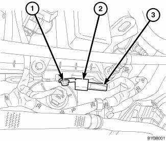
Fig. 7: Capacitor 2.4L
- - Bolt
- - Capacitor
- - Connector
1. Install ignition coil capacitor (2) and bolt (1), tighten bolt to 10 N.m (88.5 ft. lbs.).
2. Connect electrical connector (3).
3. Install engine cover.
4. Connect negative battery cable, tighten nut to 5 N.m (45 in. lbs.).
2.7L 1st
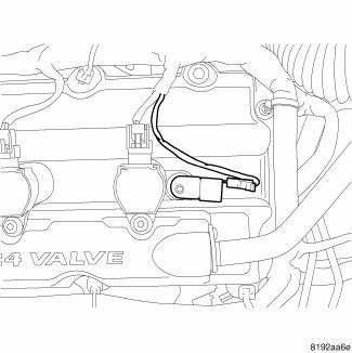
Fig. 8: 1st Ignition Capacitor - 2.7L
1. Install ignition coil capacitor and nut.
2. Tighten nut to 10 N.m (88.5 in. lbs.).
3. Attach electrical connector to capacitor.
4. Connect negative battery cable and tighten nut to 5 N.m (45 in. lbs.).
2.7L 2nd
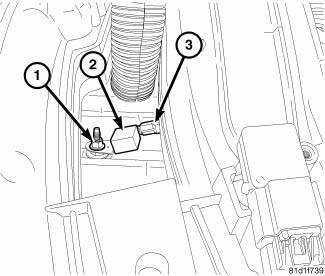
Fig. 9: 2nd Ignition Capacitor - 2.7L
1. Install ignition coil capacitor (2) and bolt (1).
2. Tighten bolt to 28 N.m (20.5 ft. lbs.).
3. Connect electrical connector (3).
4. Connect negative battery cable and tighten nut to 5 N.m (45 in. lbs.).
3.5L
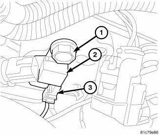
Fig. 10: Ignition Capacitor - 3.5L
1. Install ignition coil capacitor (2) and bolt (1).
2. Tighten bolt to 28 N.m (20.5 ft. lbs.).
3. Connect electrical connector (3).
4. Connect negative battery cable and tighten nut to 5 N.m (45 in. lbs.).
 Removal
2.4L
Fig. 3: Capacitor 2.4L
- Bolt
- Capacitor
- Connector
1. Disconnect and isolate negative battery cable at battery.
2. Remove engine cover.
3. Remove electrical connector (3).
...
 Coil, ignition
...
See also:
Fluid
STANDARD PROCEDURE
FLUID LEVEL CHECKING
The fluid required for this transaxle is Mopar ATF+4 (Automatic Transmission
Fluid). Use of improper or
substitute fluids can cause shift problems and/or t ...
Switch, defogger, rear
DESCRIPTION
Fig. 5: EBL Switch (MTC)
NOTE: Manual tri-zone temperature A/C-heater control shown in
illustration. Other A/Cheater
controls similar.
The momentary push-button swi ...
Installation
WITH FOOT LEVER
1. Pass most of the front parking brake cable down through the access hole in
the floor pan from inside the
vehicle.
Fig. 195: CABLE HOUSING RETAINED IN LEVER
2. Insert the lev ...
