Dodge Journey: Description, Operation
DESCRIPTION

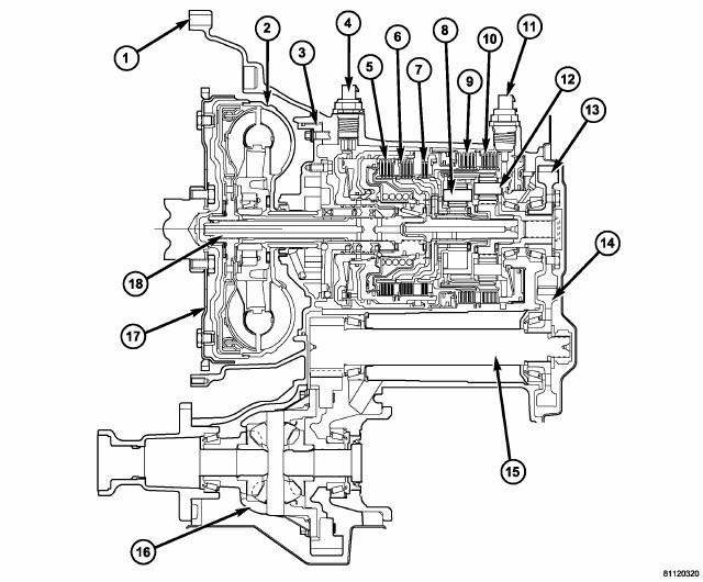
Fig. 1: Identifying 41TE Automatic Transaxle Components
- - TRANSAXLE CASE
- - TORQUE CONVERTER
- - OIL PUMP
- - INPUT SPEED SENSOR
- - UNDERDRIVE CLUTCH
- - OVERDRIVE CLUTCH
- - REVERSE CLUTCH
- - FRONT PLANET CARRIER
- - 2/4 CLUTCH
- - L/R CLUTCH
- - OUTPUT SPEED SENSOR
- - REAR PLANET CARRIER/OUTPUT SHAFT
- - OUTPUT SHAFT GEAR
- - TRANSFER SHAFT GEAR
- - TRANSFER SHAFT
- - DIFFERENTIAL
- - CONVERTER DRIVE PLATE
- - INPUT SHAFT
The 41TE is a four-speed transaxle that is a conventional hydraulic/mechanical assembly with an integral differential, and is controlled with adaptive electronic controls and monitors. The hydraulic system of the transaxle consists of the transaxle fluid, fluid passages, hydraulic valves, and various line pressure control components. An input clutch assembly which houses the underdrive, overdrive, and reverse clutches is used. It also utilizes separate holding clutches: 2nd/4th gear and Low/Reverse. The primary mechanical components of the transaxle consist of the following:
- Three multiple disc input clutches
- Two multiple disc holding clutches
- Four hydraulic accumulators
- Two planetary gear sets
- Hydraulic oil pump
- Valve body
- Solenoid/Pressure switch assembly
- Integral differential assembly
Control of the transaxle is accomplished by fully adaptive electronics. Optimum shift scheduling is accomplished through continuous real-time sensor feedback information provided to the Powertrain Control Module (PCM) or Transmission Control Module (TCM).
The PCM/TCM is the heart of the electronic control system and relies on information from various direct and indirect inputs (sensors, switches, etc.) to determine driver demand and vehicle operating conditions. With this information, the PCM/TCM can calculate and perform timely and quality shifts through various output or control devices (solenoid pack, transmission control relay, etc.).
The PCM/TCM also performs certain self-diagnostic functions and provides comprehensive information (sensor data, DTC's, etc.) which is helpful in proper diagnosis and repair. This information can be viewed with the scan tool.
TRANSAXLE IDENTIFICATION

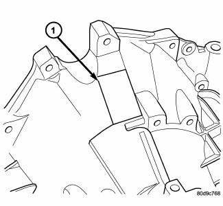
Fig. 2: Locating Transaxle Identification Label
- - IDENTIFICATION LABEL
The 41TE transaxle is identified by a barcode label (1) that is fixed to the transaxle.

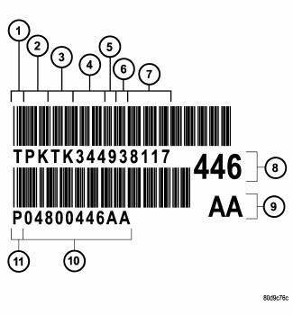
Fig. 3: Identification Label Breakdown
- - T=TRACEABILITY
- - SUPPLIER CODE (PK=KOKOMO)
- - COMPONENT CODE (TK=KOKOMO TRANSMISSION)
- - BUILD DAY (344=DEC. 9)
- - BUILD YEAR (9=1999)
- - LINE/SHIFT CODE (3=3RD SHIFT)
- - BUILD SEQUENCE NUMBER
- - LAST THREE OF P/N
- - ALPHA
- - TRANSAXLE PART NUMBER
- - P=PART NUMBER
The label contains a series of digits that can be translated into useful information such as transaxle part number, date of manufacture, manufacturing origin, plant shift number, build sequence number, etc. Refer to Fig. 3 for identification label breakdown.
If the tag is not legible or missing, the "PK" number, which is stamped into the transaxle case behind the transfer gear cover, can be referred to for identification. This number differs slightly in that it contains the entire transaxle part number, rather than the last three digits.
OPERATION
Transmission output is directed to an integral differential by a transfer gear system in the following input-to-output ratios:
First
- 2.84 : 1
Second
- 1.57 : 1
Third
- 1.00 : 1
Overdrive
- 0.69 : 1
Reverse
- 2.21 : 1
See also:
Removal
1. Raise and support vehicle.
NOTE: Perform 2 through 5 on each side of vehicle to complete pad set
removal.
Fig. 124: TIRE AND WHEEL MOUNTING
2. Remove wheel mounting nuts (3), then tire ...
Vehicle emission control information label, trip definition
VEHICLE EMISSION CONTROL INFORMATION LABEL
All vehicles have a Vehicle Emission Control Information (VECI) Label.
Chrysler permanently attaches the
label in the engine compartment. It cannot be re ...
Seal, axle drive shaft
REMOVAL
Fig. 197: Axle Shaft Seal Removal
1. Remove axle shaft.
2. Insert a flat-blade pry tool (2) at outer edge of axle shaft seal (1).
3. Tap on the pry tool (2) with a small hammer and ...


