Dodge Journey: Pulley, idler
Removal
2.4L ENGINE

Fig. 30: ACCESSORY DRIVE BELT IDLER PULLEY - 2.4L
- - UPPER PULLEY
- - LOWER PULLEY
1. Remove accessory drive belt.
2. Remove upper idler pulley (1) and bolt.
3. Remove lower idler pulley (2) and bolt.
3.5L ENGINE

Fig. 31: IDLER PULLEY - 3.5L
- - IDLER PULLEY
- - BOLT
1. Remove accessory drive belt.
2. Remove mounting bolt (2) and idler pulley (1).
2.0L DIESEL ENGINE
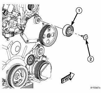
Fig. 32: IDLER PULLEY - 2.0L DIESEL
- - IDLER PULLEY
- - DUST SHIELD
- - CAP
- - BOLT
1. Remove accessory drive belt.
2. Remove bolt (4), cap (3), idler pulley (1), and dust shield (2).
Installation
2.4L ENGINE
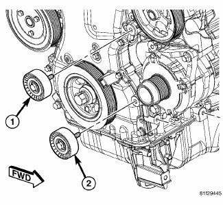
Fig. 33: ACCESSORY DRIVE BELT IDLER PULLEY - 2.4L
- - UPPER PULLEY
- - LOWER PULLEY
1. Position lower idler pulley (2) and bolt.
2. Tighten bolt to 35 N.m (25 ft. lbs.).
3. Position upper idler pulley (1) and bolt.
4. Tighten bolt to 35 N.m (25 ft. lbs.).
5. Install accessory drive belt. See Installation .
3.5L ENGINE

Fig. 34: IDLER PULLEY - 3.5L
- - IDLER PULLEY
- - BOLT
1. Position idler pulley and bolt.
2. Tighten bolt to 35 N.m (25 ft. lbs.).
3. Install accessory drive belt.
2.0L DIESEL ENGINE
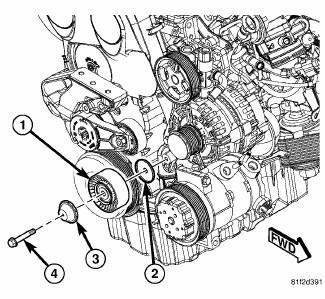
Fig. 35: IDLER PULLEY - 2.0L DIESEL
- - IDLER PULLEY
- - DUST SHIELD
- - CAP
- - BOLT
1. Position bolt (4), cap (3), idler pulley (1) and dust shield (2) on front engine cover.
2. Tighten bolt to 35 N.m (25 ft.lbs.).
3. Install accessory drive belt.
 Belt, serpentine, power steering
Removal
2.7L ENGINE
Fig. 28: STRETCH TO FIT POWER STEERING BELT REMOVAL
- POWER STEERING PULLEY
- STRETCH TO FIT POWER STEERING BELT
1. Raise and support the vehicle.
2. Remove RH whee ...
 Ensioner, belt
Removal
2.4L ENGINE
Fig. 36: ACCESSORY DRIVE BELT - WORLD ENGINE
- POWER STEERING PUMP
- ACCESSORY DRIVE BELT
- GENERATOR
- CRANKSHAFT PULLEY
- LOWER IDLER PULLEY
- CRANKSHAFT PULLEY ...
See also:
Description
Fig. 161: Rear Heater AC Housing Description
Models with the rear heating-A/C system use a rear heater-A/C housing (1)
that combines A/C and heating
capabilities into a single unit mounted withi ...
Pump, engine oil
Removal
Fig. 275: Oil Pump & Pick-up Tube
- BOLTS
- O-RING
- PICK-UP TUBE
- BOLT
- OIL PUMP
NOTE: The oil pump pressure relief valve can be serviced by removing
the oil pan ...
Diagnosis and Testing, Removal, Installation
DIAGNOSIS AND TESTING
INSTRUMENT CLUSTER
As a quick diagnosis, the cluster will perform a functional check of the
odometer display, transmission range
display and warning indicators after the ign ...
