Dodge Journey: Standard Procedure
MASTER CYLINDER BLEEDING
1. Clamp the master cylinder in a vise with soft-jaw caps.

Fig. 88: BLEEDING MASTER CYLINDER WITH ABS
2. Thread a Bleeder Tube (2), Special Tool 8358-1, into the primary and secondary ports. Tighten bleeder tube nuts to 17 N.m (150 in. lbs.).
3. Flex each Bleeder Tube and place the open ends into the neck of the master cylinder reservoir. Position the open ends of the tubes into the reservoir so their outlets are below the surface of the brake fluid in the reservoir when filled.
NOTE: Make sure the ends of the Bleeder Tubes stay below the surface of the brake fluid in the reservoir at all times during the bleeding procedure.
4. Fill the brake fluid reservoir with fresh Mopar Brake Fluid DOT 3 Motor Vehicle, or equivalent.
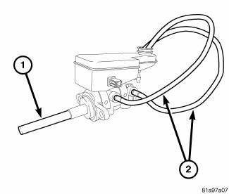
Fig. 89: BLEEDING MASTER CYLINDER WITH ABS
5. Using an appropriately sized wooden dowel as a pushrod (1), slowly press the pistons inward discharging brake fluid through the Bleeder Tubes (2), then release the pressure, allowing the pistons to return to the released position. Repeat this several times until all air bubbles are expelled from the master cylinder bore and Bleeder Tubes.
6. Remove the Bleeder Tubes from the master cylinder and plug the master cylinder outlet ports.
7. Install the fill cap on the reservoir.
8. Remove the master cylinder from the vise.
9. Install the master cylinder on the vehicle.
 Description, Operation
DESCRIPTION
Fig. 87: PRIMARY AND SECONDARY BRAKE TUBES
All master cylinders (2) are a two-outlet design and the brake tubes from
these primary and secondary outlet
ports lead directly to the In ...
 Removal
LEFT-HAND-DRIVE
CAUTION: The vacuum in the power brake booster must be depleted
before removing
the master cylinder to avoid damaging the master cylinder and to prevent
inhalation of ...
See also:
TIRE PRESSURE MONITOR SYSTEM (TPMS)
The Tire Pressure Monitor System (TPMS) will warn the
driver of a low tire pressure based on the vehicle recommended
cold placard pressure.
The tire pressure will vary with temperature by about
1 ...
REPLACEMENT PARTS
Use of genuine MOPAR parts for normal/scheduled
maintenance and repairs is highly recommended to ensure
the designed performance. Damage or failures
caused by the use of non-MOPAR parts for mainten ...
Description, Operation
DESCRIPTION
Two unique brake lamp switches are used in this vehicle, depending upon
whether the vehicle was built during
early or late production. These switches are not interchangeable and both a ...
