Dodge Journey: Pulley, idler
Removal
2.4L ENGINE

Fig. 30: ACCESSORY DRIVE BELT IDLER PULLEY - 2.4L
- - UPPER PULLEY
- - LOWER PULLEY
1. Remove accessory drive belt.
2. Remove upper idler pulley (1) and bolt.
3. Remove lower idler pulley (2) and bolt.
3.5L ENGINE

Fig. 31: IDLER PULLEY - 3.5L
- - IDLER PULLEY
- - BOLT
1. Remove accessory drive belt.
2. Remove mounting bolt (2) and idler pulley (1).
2.0L DIESEL ENGINE
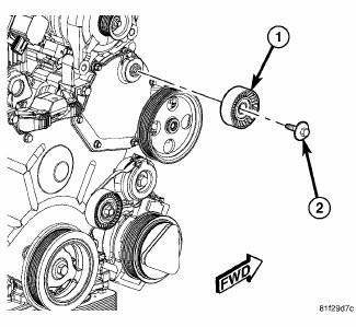
Fig. 32: IDLER PULLEY - 2.0L DIESEL
- - IDLER PULLEY
- - DUST SHIELD
- - CAP
- - BOLT
1. Remove accessory drive belt.
2. Remove bolt (4), cap (3), idler pulley (1), and dust shield (2).
Installation
2.4L ENGINE
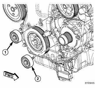
Fig. 33: ACCESSORY DRIVE BELT IDLER PULLEY - 2.4L
- - UPPER PULLEY
- - LOWER PULLEY
1. Position lower idler pulley (2) and bolt.
2. Tighten bolt to 35 N.m (25 ft. lbs.).
3. Position upper idler pulley (1) and bolt.
4. Tighten bolt to 35 N.m (25 ft. lbs.).
5. Install accessory drive belt. See Installation .
3.5L ENGINE

Fig. 34: IDLER PULLEY - 3.5L
- - IDLER PULLEY
- - BOLT
1. Position idler pulley and bolt.
2. Tighten bolt to 35 N.m (25 ft. lbs.).
3. Install accessory drive belt.
2.0L DIESEL ENGINE
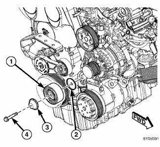
Fig. 35: IDLER PULLEY - 2.0L DIESEL
- - IDLER PULLEY
- - DUST SHIELD
- - CAP
- - BOLT
1. Position bolt (4), cap (3), idler pulley (1) and dust shield (2) on front engine cover.
2. Tighten bolt to 35 N.m (25 ft.lbs.).
3. Install accessory drive belt.
 Belt, serpentine, power steering
Removal
2.7L ENGINE
Fig. 28: STRETCH TO FIT POWER STEERING BELT REMOVAL
- POWER STEERING PULLEY
- STRETCH TO FIT POWER STEERING BELT
1. Raise and support the vehicle.
2. Remove RH whee ...
 Ensioner, belt
Removal
2.4L ENGINE
Fig. 36: ACCESSORY DRIVE BELT - WORLD ENGINE
- POWER STEERING PUMP
- ACCESSORY DRIVE BELT
- GENERATOR
- CRANKSHAFT PULLEY
- LOWER IDLER PULLEY
- CRANKSHAFT PULLEY ...
See also:
Disassembly
Fig. 229: Snap Ring At Output Shaft
1. Using Snap Ring Pliers (1) remove the snap ring (2) from the output shaft
# 2.
Fig. 230: Bearing From Cluster Shaft
2. Using a press, blocks, Bearing Sp ...
Standard Procedure
MASTER CYLINDER BLEEDING
1. Clamp the master cylinder in a vise with soft-jaw caps.
Fig. 88: BLEEDING MASTER CYLINDER WITH ABS
2. Thread a Bleeder Tube (2), Special Tool 8358-1, into the primary ...
Removal
1. Disconnect and isolate battery negative cable from battery post.
Fig. 70: BRAKE PEDAL HOLDING TOOL
2. Using a brake pedal holding tool as shown, depress brake pedal past its
first inch of tra ...
