Dodge Journey: Cover(s), cylinder head, left
REMOVAL
1. Disconnect negative battery cable.
2. Disconnect electrical connectors from ignition coils and capacitor. Reposition electrical harness.
3. Remove ground strap from cylinder head cover stud.

Fig. 118: Engine Harness Retaining Clips
- - Left cylinder head cover engine harness retainers
- - Right cylinder head cover engine harness retainers
- - Left engine harness
- - Makeup air hose
- - PCV Hose
- - Right engine harness
4. Disconnect engine harness retaining clips (1) from cylinder head cover studs. Position the engine harness (3) aside.
5. Remove fastener attaching ignition coil capacitor.
6. Remove ignition coils.
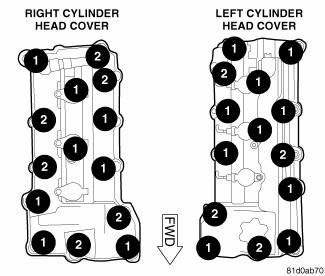
Fig. 119: Cylinder Head Cover Fasteners
- - DOUBLE ENDED STUDS
- - BOLTS
7. Loosen all left cylinder head cover fasteners.
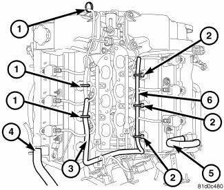
Fig. 120: Engine Harness Retaining Clips
- - Left cylinder head cover engine harness retainers
- - Right cylinder head cover engine harness retainers
- - Left engine harness
- - Makeup air hose
- - PCV Hose
- - Right engine harness
8. Disconnect the makeup air hose (4).
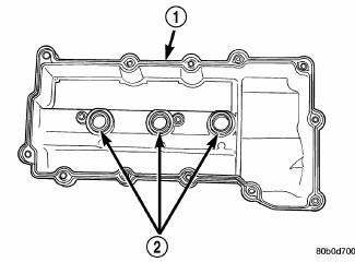
Fig. 121: Cylinder Head Cover Gasket & Spark Plug Seals
- - ONE PIECE GASKET
- - SPARK PLUG WELL SEALS
NOTE: Cylinder head cover attaching bolts are captured to the cover.
CAUTION: Make certain the double ended studs in the center of the cylinder head cover are loose before attempting to remove cover.
9. Remove the left cylinder head cover (1).
INSTALLATION

Fig. 122: Cylinder Head Cover Gasket & Spark Plug Seals
- - ONE PIECE GASKET
- - SPARK PLUG WELL SEALS
1. Clean cylinder head cover and both sealing surfaces. Inspect and replace gaskets (1) as necessary.

Fig. 123: Cylinder Head Cover Fasteners
- - DOUBLE ENDED STUDS
- - BOLTS
2. Install cylinder head cover and hand start all fasteners. Verify that all double-ended studs are in the correct locations (1).
3. Tighten cylinder head cover attaching bolts and double-ended studs to 12 N.m (105 in. lbs.).

Fig. 124: Engine Harness Retaining Clips
- - Left cylinder head cover engine harness retainers
- - Right cylinder head cover engine harness retainers
- - Left engine harness
- - Makeup air hose
- - PCV Hose
- - Right engine harness
4. Reposition the left engine harness (3), and install the left engine harness retainers (1) to the double-ended studs.
5. Install the ignition coils.
6. Install ignition coil capacitor and fastener.
7. Reconnect all electrical connectors.
8. Install ground strap to cylinder head cover stud.

Fig. 125: Engine Harness Retaining Clips
- - Left cylinder head cover engine harness retainers
- - Right cylinder head cover engine harness retainers
- - Left engine harness
- - Makeup air hose
- - PCV Hose
- - Right engine harness
9. Install the makeup air hose.
10. Connect negative battery cable.
 Camshaft, engine
DESCRIPTION
Fig. 108: Camshaft & Valvetrain Components
- CAMSHAFT BEARING CAP - INTAKE
- CAMSHAFT BEARING CAP - EXHAUST
- CAMSHAFT - EXHAUST
- ROCKER ARM
- HYDRAULIC LIFTER
- CYLI ...
 Cover(s), cylinder head, right
REMOVAL
1. Disconnect negative battery cable.
Fig. 126: Engine Harness Retaining Clips
- Left cylinder head cover engine harness retainers
- Right cylinder head cover engine harness retainer ...
See also:
Standard procedure
REFRIGERANT SYSTEM SERVICE EQUIPMENT
WARNING: Refer to the applicable warnings and cautions for this
system before
performing the following operation. Failure to follow these instructio ...
Reservoir, brake master cylinder
Removal
CAUTION: If at any time the master cylinder is loosened or
removed, you must
perform the master cylinder installation procedure to ensure that the
seal
(o-ring) is still ...
Description, Operation
DESCRIPTION
Two unique brake lamp switches are used in this vehicle, depending upon
whether the vehicle was built during
early or late production. These switches are not interchangeable and both a ...
