Dodge Journey: Standard procedure
PARKING BRAKE CABLE TENSION RELEASE - FOOT LEVER
Use the following procedure to release the tension from the parking brake cables and the automatic adjuster in the parking brake lever (pedal) mechanism when required.
1. Release the parking brake.
2. Raise the vehicle to a comfortable working position and support.
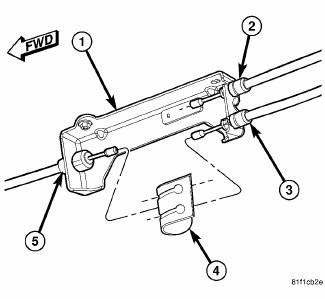
Fig. 176: PARKING BRAKE CABLE EQUALIZER
3. Wipe the parking brake cable strands (front and both rear) clean where visible at the intermediate bracket.
CAUTION: Do not use any type of sharp instrument to hold the cable strand in place. Damage to the cable strand or coating can occur.
4. Pull rearward on the equalizer (4) until the front cable stops, then grasp the front cable (5) strand and hold it in this position. Disconnect the equalizer from the front cable strand.
5. Release the front cable strand allowing the lever automatic self-adjusting mechanism to pull the front cable strand forward. This action allows the adjuster mechanism to rotate around to its stop, removing tension from the adjuster and front parking brake cable.
PARKING BRAKE CABLE TENSION RELEASE - HAND LEVER
1. Release the parking brake.
2. Block the tire and wheel assemblies so the vehicle does not move once the parking brake lever is released.
3. Release the parking brake.
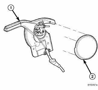
Fig. 177: HAND LEVER COVER MOUNTING
4. Remove the cover from the side of the parking brake lever. To remove the cover, unclip it at the top and rotate it counterclockwise.
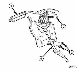
Fig. 178: CABLE MOUNTING TO HAND LEVER
5. Place the parking brake lever (1) in the fully released (down) position.
6. Loosen the adjusting nut (2) on the end of the front parking brake cable. Back it off to the end of the cable.
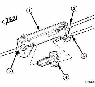
Fig. 179: CABLE EQUALIZER/TENSIONER
7. If the cable equalizer/bent nail tensioner needs to be removed, perform the following:
- Raise the vehicle to a comfortable working position and support.
- Remove the parking brake cable equalizer/bent nail tensioner (4) from the three parking brake cables (2, 3, 5).
PARKING BRAKE CABLE TENSION RESET - FOOT LEVER
1. Raise the vehicle to a comfortable working position and support.
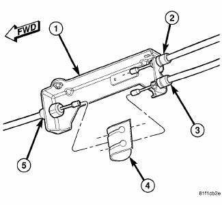
Fig. 180: PARKING BRAKE CABLE EQUALIZER
2. Wipe the front parking brake cable strand clean at the intermediate bracket (1) area.
CAUTION: Do use any type of sharp instrument directly on the cable strand to hold it in place. Damage to the cable strand or coating can occur.
3. Clamp an appropriate pair of pliers on the front parking brake cable button (2) only and pull the cable stand rearward until it stops, then grasp the front cable strand and hold it in this position. Remove the pliers from the button.
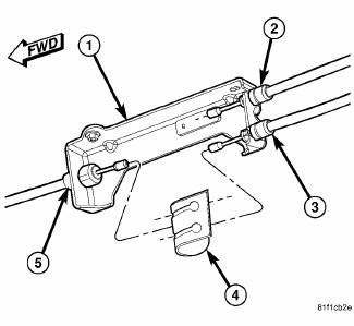
Fig. 181: PARKING BRAKE CABLE EQUALIZER
4. While holding the front cable in this position, install the equalizer (2) (attached to both rear cables) on the front parking brake cable.
5. Release the grasp on the front parking brake cable.
6. Lower the vehicle.
7. Apply and release the parking brake lever one time. This will seat the parking brake cables and allow the auto adjuster in the parking brake lever mechanism to correctly tension the parking brake cables.
PARKING BRAKE CABLE TENSION RESET - HAND LEVER
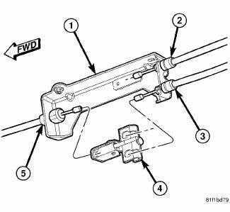
Fig. 182: CABLE EQUALIZER/TENSIONER
1. If the cable equalizer/bent nail tensioner needs to be installed on the cables, perform the following:
- Raise the vehicle to a comfortable working position and support.
- Connect the parking brake cable equalizer/bent nail tensioner (4) to the three parking brake cables (2, 3, 5).
- Remove any slack from the parking brake cables by pushing the front cable strand forward into the housing until slack is removed.
- Lower the vehicle.
2. If not installed during Step (1), make sure the parking brake cable equalizer/bent nail tensioner is attached to all three parking brake cables 3. Make sure that the front parking brake cable is properly aligned and installed on the cable track of the parking brake lever.
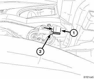
Fig. 183: CABLE STUD-TO-NUT DIMENSION
NOTE: Actuating the parking brake lever to its fully applied position one time after tightening the adjustment nut will yield (stretch) the bent nail portion of the equalizer approximately 1/4 inch (6 mm). This process will correctly set the parking brake cable tension.
4. Adjust parking brake cable tension using the following steps:
- Make sure the parking brake lever in the fully released (down) position.
- While maintaining tension on the cable, tighten the adjusting nut (2) on the front parking brake cable until 34 millimeters (1.34 in.) of thread (1) is out past the end of the adjustment nut.
- Actuate the parking brake lever to its fully applied position one time, then reposition it to its fully released (down) position.
5. Raise the vehicle to a point where the rear wheels just clear the floor.
6. Check the rear wheels of the vehicle; they should rotate freely without dragging.
7. Apply the parking brake. Check the rear wheels of the vehicle. They should not rotate.
8. Return the parking brake lever to its fully released (down) position and check the rear wheels. They should rotate freely without dragging.
9. Apply the parking brake.
10. Lower the vehicle.
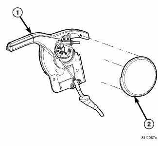
Fig. 184: HAND LEVER COVER MOUNTING
11. Install the cover on the side of the parking brake lever.
CABLE END CLEANING AND LUBRICATION
Periodic cleaning and lubrication can be done to ensure proper operation of the parking brake cables. This procedure applies to the trailing end of all parking brake cables.
CAUTION: If a liquid cleaner is necessary, use a cleaner such as Mopar Non- Chlorinated Brake Parts Cleaner or equivalent.
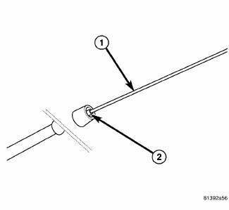
Fig. 185: Areas To Be Cleaned And Lubricated
- - STRAND AREA
- - SEAL AREA
1. Using an appropriate bristle brush, clean the cable strand (1) in the area that retracts into the cable housing when the parking brake lever is applied.
2. Clean the cable seal area (2) at the end of the cable housing.
3. Lubricate the cleaned area with a general purpose grease lubricant.
 Description
The parking brake consists of the following components:
Foot-operated parking brake lever *
Cables (front, left rear, right rear)
Cable equalizer
Caliper with Integral Parking Brake (IPB)
...
See also:
Duct, instrument panel
Removal
WARNING: Disable the airbag system before attempting any steering
wheel, steering
column or instrument panel component diagnosis or service. Disconnect
and isolate the negati ...
TIRE PRESSURE MONITOR SYSTEM (TPMS)
The Tire Pressure Monitor System (TPMS) will warn the
driver of a low tire pressure based on the vehicle recommended
cold placard pressure.
The tire pressure will vary with temperature by about
1 ...
Removal
1. Remove the engine cover.
2. Release fuel pressure.
3. Disconnect negative battery cable.
4. Drain cooling system.
5. Evacuate the A/C system using a suitable refrigerant recovery machi ...

