Dodge Journey: Removal
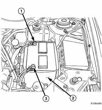
Fig. 431: Identifying Battery Cables
- - BATTERY POSITIVE CABLE
- - THERMO-WRAP
- - BATTERY NEGATIVE CABLE
NOTE: If valve body is replaced or reconditioned, the PCM Quick Learn Procedure must be performed.
NOTE: The Engine Cradle Crossmember assembly must be partially lowered to gain access to and remove the Valve Body assembly.
1. Disconnect battery negative cable.
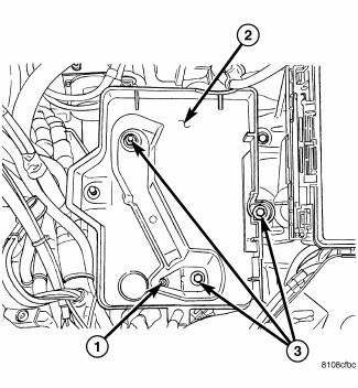
Fig. 432: Removing/Installing Battery & Tray
- - DRAIN HOLE/HOSE ATTACHMENT
- - BATTERY TRAY
- - BOLTS
2. Remove battery and tray.
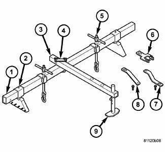
Fig. 433: Installing Overhead Powertrain Support Fixture
- - SUPPORT TUBE 8534-1
- - BRACKET/SLEEVE 8534-2
- - CROSS-BAR 8534-3
- - CLAMP 8534-5
- - LIFT HOOK ASSEMBLY
- - LIFT BRACKET/BOLT 8534-15
- - LIFT BRACKET/BOLT 8534-7
- - LIFT BRACKET/BOLT 8534-8
- - SUPPORT LEG 8534-4
3. Install overhead powertrain support fixture (Tool 8534B and adapter kit 8534-12)
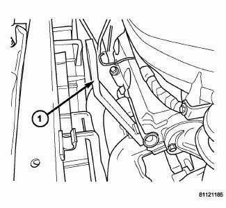
Fig. 434: Installing Lift/Support Bracket 8534-8
- - BRACKET 8534-8
4. Remove engine oil dipstick tube-to-cylinder head fastener. Install lift/support bracket 8534-8 and secure with dipstick tube bolt.
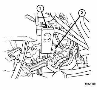
Fig. 435: Installing Lift/Support Bracket 8534-7 & Bolt
- - BRACKET 8534-7
- - REAR CYLINDER HEAD
5. Disconnect coolant temperature sensor (at thermostat housing). Remove engine harness-to-cylinder head bolt. Position harness out of the way. Install and secure lift/support bracket and bolt 8534-7
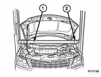
Fig. 436: Identifying Support Tube & Sleeve/Bracket
- - SUPPORT TUBE 8534-1
- - BRACKET/SLEEVE 8534-2
6. Assemble cross-bar 8534-3, clamp 8534-5 and support leg 8534-4 to support tube, allowing support leg to rest on radiator upper support.
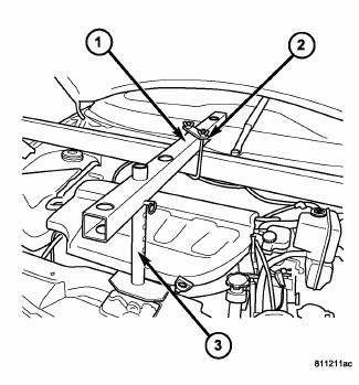
Fig. 437: Identifying Crossbar, Support Leg, & Clamp
- - CROSS-BAR 8534-3
- - CLAMP 8534-5
- - SUPPORT LEG 8534-4
7. Tighten cross-bar-to-support tube clamp 8534-5 , as well as mounting bracket/sleeve 8534-2 thumb screw and hex nut to secure fixture.
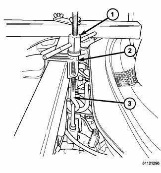
Fig. 438: Installing Bracket/Hook Assemblies
- - T-HANDLE 8534-14
- - LIFTING BRACKET 8534-13
- - HOOK ASSEMBLY 8534-11
8. Install lift bracket/hook assemblies.
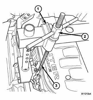
Fig. 439: Identifying T-Handle, Lifting Bracket, & Hook Assembly
- - LIFTING BRACKET 8534-13
- - T-HANDLE 8534-14
- - HOOK ASSEMBLY 8534-11
9. Tighten t-handles just enough to build tension between the fixture and drivetrain.
10. Disconnect gearshift cable from manual valve lever.
11. Remove manual valve lever from manual shaft.
12. Raise vehicle on hoist.
13. Remove engine mount (front and rear) to engine cradle crossmember nuts.
14. Place scribe marks at engine cradle crossmember and body for alignment upon reassembly.
15. Support cradle at rear with screw jack or equivalent. Partially remove engine cradle crossmember-to-body bolts, lowering cradle at rear enough to facilitate cradle pivoting.
16. Support cradle at front with screw jack or equivalent. Remove engine cradle crossmember-to-body bolts.
Lower cradle at front approximately 10 inches to facilitate valve body removal.
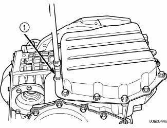
Fig. 440: Identifying Oil Pan Bolts
- - OIL PAN BOLTS (USE RTV UNDER BOLT HEADS)
17. Remove oil pan bolts.
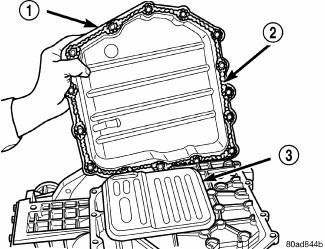
Fig. 441: Removing/Installing Oil Pan
- - OIL PAN
- - 1/8 INCH BEAD OF RTV SEALANT
- - OIL FILTER
18. Remove oil pan.
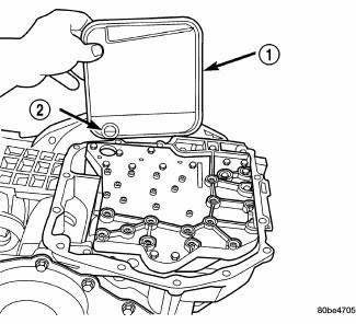
Fig. 442: Identifying Filter & O-Ring
- - OIL FILTER
- - O-RING
19. Remove oil filter.
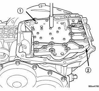
Fig. 443: Identifying Valve Body-To-Transaxle Case Bolts
- - VALVE BODY ATTACHING BOLTS (18)
- - VALVE BODY
20. Remove the valve body-to-transaxle case bolts.
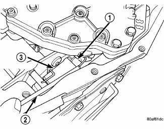
Fig. 444: Removing/Installing Park Rod Rollers
- - PARK SPRAG ROLLERS
- - SCREWDRIVER
- - PARK SPRAG GUIDE BRACKET
NOTE: To ease removal of the valve body, turn the manual valve lever fully clockwise to low or first gear.
21. Remove park rod rollers from guide bracket.
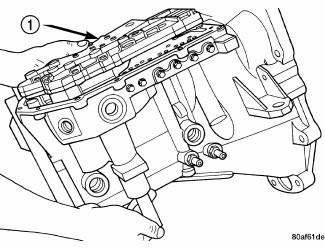
Fig. 445: Removing/Installing Valve Body
- - VALVE BODY
22. Remove valve body from transaxle. Note position of accumulator and springs upon removal for assembly reference.
CAUTION: The valve body manual shaft pilot may distort and bind the manual valve if the valve body is mishandled or dropped.
 Description, Operation
DESCRIPTION
Fig. 430: Identifying Valve Body Assembly
- VALVE BODY
- T/C REGULATOR VALVE
- L/R SWITCH VALVE
- CONVERTER CLUTCH CONTROL VALVE
- MANUAL VALVE
- CONVERTER CLUTCH SWITCH V ...
 Disassembly
NOTE: Cleanliness through entire disassembly and assembly of the valve
body cannot
be overemphasized. When disassembling, each part should be washed in a
suitable solvent, then dried by comp ...
See also:
Link, stabilizer bar
REMOVAL
1. Raise and support the vehicle.
Fig. 60: TIRE AND WHEEL MOUNTING
2. Remove the wheel mounting nuts (3), then the tire and wheel assembly (1).
Fig. 61: Strut Mounting To Knuckle
3. W ...
Module, power, front blower motor
DESCRIPTION
Fig. 27: Blower Mtr Pwr Module
A blower motor power module is used on this model when equipped with the
automatic temperature control (ATC) heating-A/C system. Models equipped with t ...
Operation
Fig. 427: Identifying Torque Converter Fluid Pressure
Operation
- APPLY PRESSURE
- THE PISTON MOVES SLIGHTLY
FORWARD
- RELEASE PRESSURE
- THE PISTON MOVES SLIGHTLY
REARWARD
The co ...
