Dodge Journey: Frame
SPECIFICATIONS
FRAME DIMENSIONS
Frame dimensions are listed in metric scale. All dimensions are from center to center of Principal Locating Point (PLP), or from center to center of PLP and fastener location.
VEHICLE PREPARATION
Position the vehicle on a level work surface. Using screw or bottle jacks, adjust the vehicle PLP heights to the specified dimension above a level work surface. Vertical dimensions can be taken from the work surface to the locations indicated were applicable.
VEHICLE PREPARATION INDEX

Fig. 27: Frame Dimensions - Side View
Fig. 28: Frame Dimensions - Bottom View
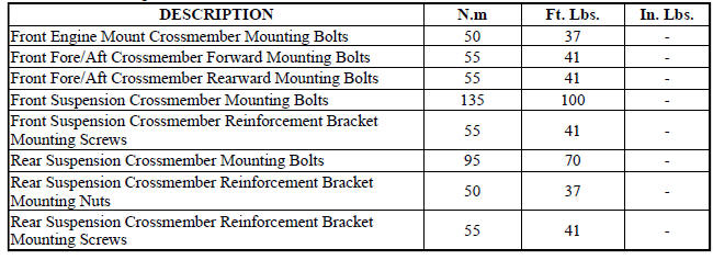
FASTENER TORQUE
 Reinforcement, bumper, rear
REMOVAL
Fig. 25: Rear Bumper Reinforcement
1. Remove rear fascia. See Removal .
2. Support bumper reinforcement (1) on a suitable lifting device.
3. Mark position of bolts (2) on frame rail ...
 Crossmember, front fore and aft
REMOVAL
1. Raise and support the vehicle.
2. If equipped, remove the engine belly pan.
Fig. 29: Removing/Installing Fore/Aft Crossmember
3. Remove the front engine mount thru-bolt (2).
Fig ...
See also:
Installation
Fig. 164: Removing/Installing Bellhousing Upper & Lower Bolts
NOTE: If transaxle assembly is being replaced or overhauled (clutch
and/or seal
replacement), it is necessary to perform th ...
EMISSIONS CONTROL SYSTEM MAINTENANCE
The Scheduled Maintenance services listed in bold type,
must be done at the times or mileages specified to ensure
the continued proper functioning of the Emissions Control
System. These, and all ot ...
Lamp, license plate
REMOVAL
BULB
Fig. 16: License Plate Lamp Bulb Socket
1. Disconnect and isolate the battery negative cable.
2. Remove the license plate lamp from the underside of the liftgate handle and
ligh ...
