Dodge Journey: Fascia, front
REMOVAL
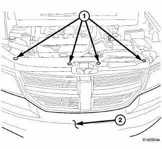
Fig. 1: Pushpins
1. Release hood latch and open hood.
2. Remove the pushpins for the fascia (2) at the radiator support.
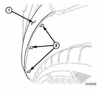
Fig. 2: Pop Rivets
3. Hoist and support vehicle on safety stands.
4. Remove the pop rivets (2) at the wheel well opening.
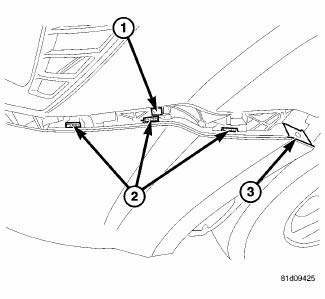
Fig. 3: Fascia Tabs & Bracket
5. Remove the Torx screw (3) at the wheel well housing.
6. Separate the fascia tabs (2) at the bracket (1).
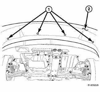
Fig. 4: Lower Pushpins
7. Remove the pushpins (1) for the fascia (2) at the lower closeout panel.
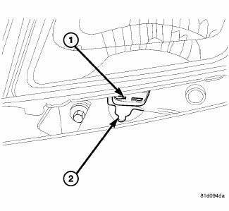
Fig. 5: Fascia & Mounting Tab
8. Slide the fascia (2) out from the mounting tab (1) under the headlamp.
9. Disengage fog lamp wire connector and side marker connector from body harness, if equipped.
10. Disengage the ambient temp sensor wire connector, if equipped.
11. Remove fascia from vehicle.
INSTALLATION
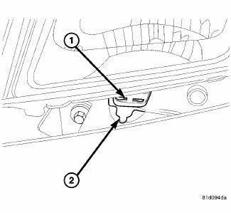
Fig. 6: Fascia & Mounting Tab
1. Install the fascia to the vehicle.
2. Reconnect the ambient temp sensor wire connector, if equipped.
3. Reconnect the fog lamp wire connector and side marker connector from body harness, if equipped.
4. Slide the fascia (2) into the mounting tab (1) under the headlamp.
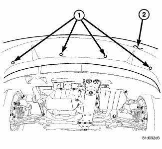
Fig. 7: Lower Pushpins
5. Install the pushpins (1) for the fascia (2) at the lower closeout panel.
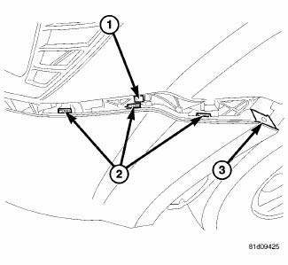
Fig. 8: Fascia Tabs & Bracket
6. Insert and snap into place the fascia tabs (2) at the bracket (1).
7. Install the Torx screw (3) at the wheel well housing.
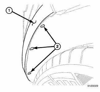
Fig. 9: Pop Rivets
8. Install the pop rivets (2) at the wheel well opening.
9. Lower the vehicle.
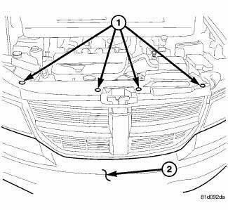
Fig. 10: Pushpins
10. Install the pushpins for the fascia (2) at the radiator support.
11. close the hood and check for proper fit.
 Bumpers
...
 Fascia, front lower, closeout
REMOVAL
Fig. 11: Lower Fascia
1. Remove fasteners (5) to lower closeout.
Fig. 12: Push Pins - Front Lower Fascia
2. Remove push pins (1) to lower closeout.
3. Remove the front lower fascia.
...
See also:
Schematics and diagrams
40/41TE - WITH VARIABLE LINE PRESSURE
Fig. 181: Identifying Line Pressure - Park & Neutral
Fig. 182: Identifying Line Pressure - Reverse
Fig. 183: Identifying Line Pressure - First Gear ( ...
Sensor, speed, input
DESCRIPTION
Fig. 369: Removing/Installing Input Speed Sensor
- INPUT SPEED SENSOR
The Input Speed Sensor (1) , is a two-wire magnetic pickup device that
generates AC signals as rotation oc ...
FREEING A STUCK VEHICLE
If your vehicle becomes stuck in mud, sand, or snow, it
can often be moved by a rocking motion. Turn your
steering wheel right and left to clear the area around the
front wheels. Then shift back an ...
