Dodge Journey: Schematics and diagrams
40/41TE - WITH VARIABLE LINE PRESSURE
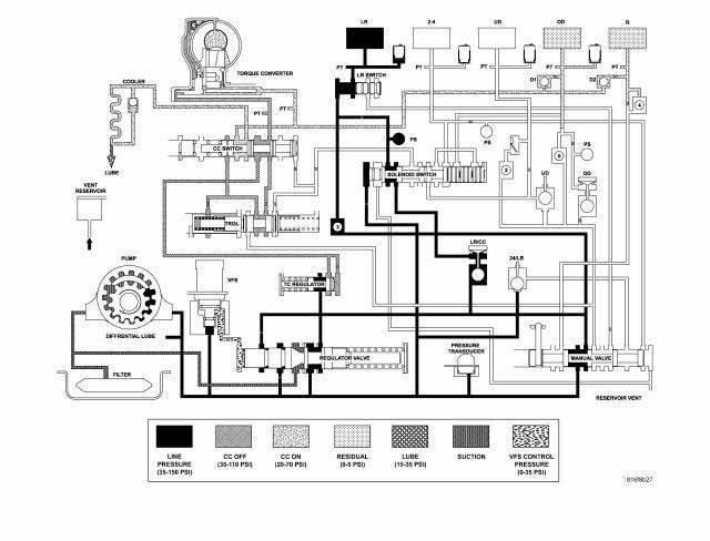
Fig. 181: Identifying Line Pressure - Park & Neutral
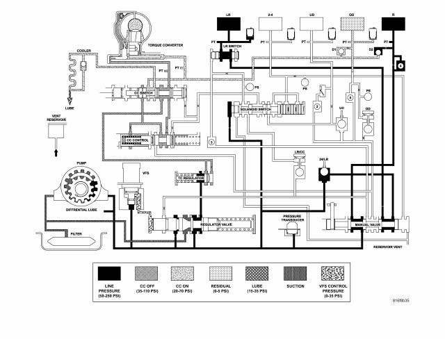
Fig. 182: Identifying Line Pressure - Reverse
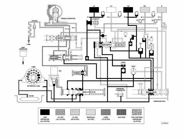
Fig. 183: Identifying Line Pressure - First Gear (Drive)
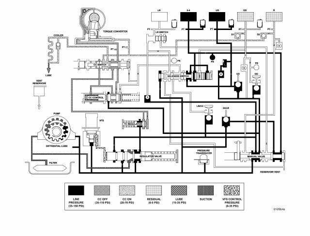
Fig. 184: Identifying Line Pressure - Second Gear (Drive)
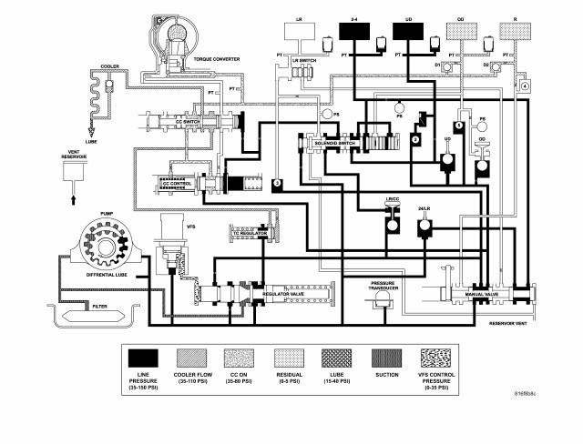
Fig. 185: Identifying Line Pressure - Second Gear EMCC (Drive)
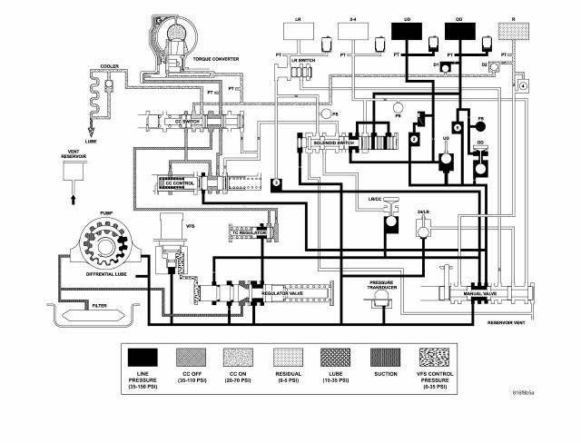
Fig. 186: Identifying Line Pressure - Direct Gear (Drive)
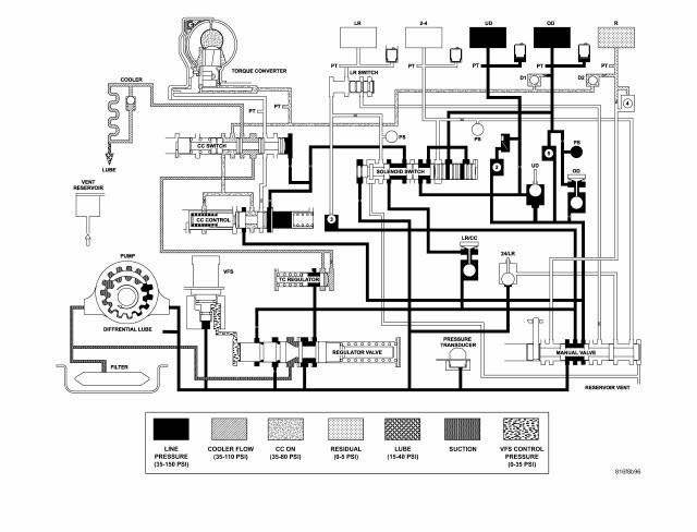
Fig. 187: Identifying Line Pressure - Direct Gear EMCC (Drive)
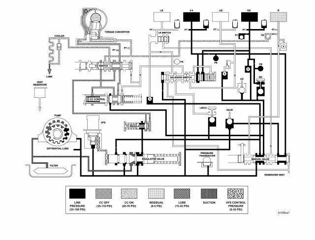
Fig. 188: Identifying Line Pressure - Fourth Gear Overdrive (Drive)
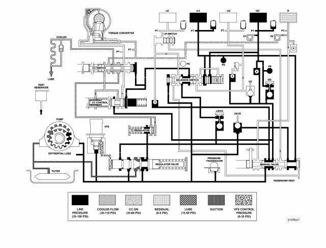
Fig. 189: Identifying Line Pressure - Fourth Gear Overdrive EMCC (Drive)
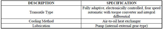
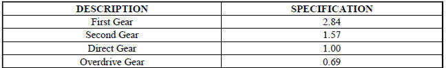
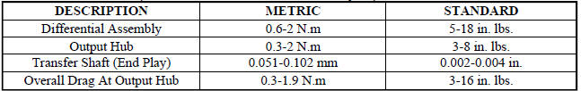
SPECIFICATIONS
GENERAL SPECIFICATIONS
GEAR RATIOS

BEARING SETTINGS (END PLAY AND TURNING TORQUE)
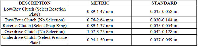
CLUTCH CLEARANCES
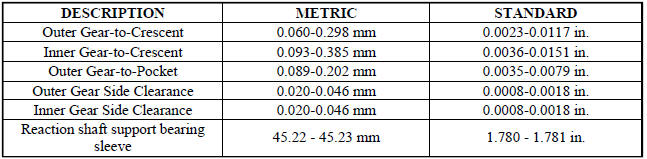
OIL PUMP CLEARANCES
INPUT SHAFT

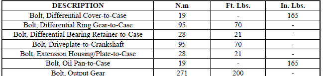
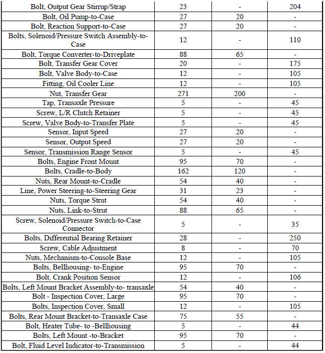
TORQUE SPECIFICATIONS
SPECIAL TOOLS
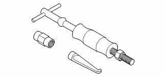
Fig. 190: Puller C-637
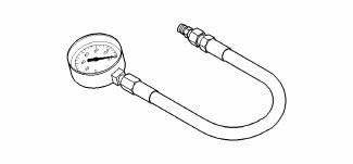
Fig. 191: Pressure Gauge (High) C-3293SP
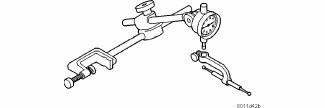
Fig. 192: Dial Indicator C-3339
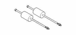
Fig. 193: Oil Pump Puller C-3752
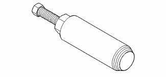
Fig. 194: Seal Puller C-3981B
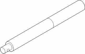
Fig. 195: Universal Handle C-4171
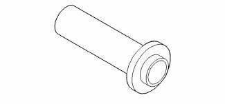
Fig. 196: Seal Installer C-4193A
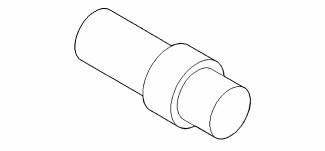
Fig. 197: Adapter C-4996
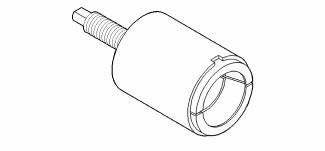
Fig. 198: Remover Kit L-4406
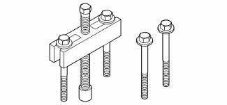
Fig. 199: Gear Puller L-4407A
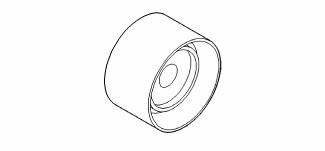
Fig. 200: Bearing Installer L-4410
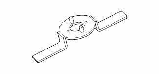
Fig. 201: Gear Checking Plate L-4432
Fig. 202: Bearing Puller L-4435
Fig. 203: Differential Tool L-4436A
Fig. 204: Special Jaw Set L-4518
Fig. 205: Installer L-4520
Fig. 206: Thrust Button L-4539-2
Fig. 207: Adapter L-4559
Fig. 208: Adapter L-4559-2
Fig. 209: Bearing Splitter P-334
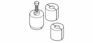
Fig. 210: Puller Set 5048
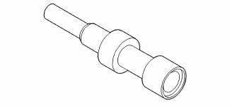
Fig. 211: Remover/Installer 5049-A
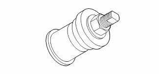
Fig. 212: Installer 5050A
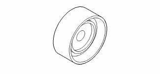
Fig. 213: Installer 5052
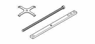
Fig. 214: Compressor 5058A
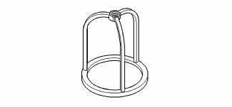
Fig. 215: Compressor 5059-A
Fig. 216: Installer 5067
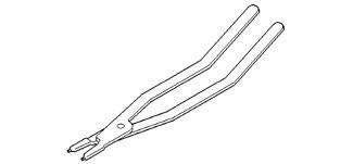
Fig. 217: Pliers 6051
Fig. 218: Installer 6052
Fig. 219: Installer 6053
Fig. 220: Button 6055
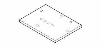
Fig. 221: Plate 6056
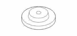
Fig. 222: Disk 6057
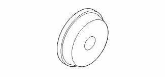
Fig. 223: Installer 6061
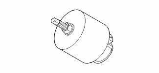
Fig. 224: Remover 6062-A
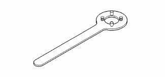
Fig. 225: Holder 6259
Fig. 226: Bolt 6260
Fig. 227: Installer 6261
Fig. 228: Tip 6268
Fig. 229: Remover/Installer 6301
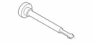
Fig. 230: Remover/Installer 6302
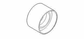
Fig. 231: Installer 6536-A

Fig. 232: Puller 7794-A
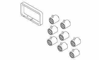
Fig. 233: End Play Socket Set 8266
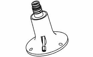
Fig. 234: Input Clutch Pressure Fixture 8391
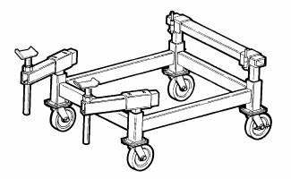
Fig. 235: Driveline Support Table 8874
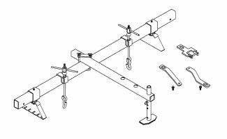
Fig. 236: Driveline Support Fixture 8534B
Fig. 237: Steering Shaft Roll Pin Remover/Installer 6831A
 Installation
Fig. 164: Removing/Installing Bellhousing Upper & Lower Bolts
NOTE: If transaxle assembly is being replaced or overhauled (clutch
and/or seal
replacement), it is necessary to perform th ...
 Accumulator
DESCRIPTION
Fig. 238: Identifying Underdrive & Overdrive Accumulators
- RETURN SPRING
- UNDERDRIVE CLUTCH ACCUMULATOR
- SEAL RING (2)
- OVERDRIVE CLUTCH ACCUMULATOR
The 41TE underd ...
See also:
Removal
Fig. 60: Support Module With Jack
- DRIVELINE MODULE
- TRANSMISSION JACK
NOTE: Rear suspension and drivetrain design require this procedure to
be performed
on a "drive-on" ...
Disassembly
NOTE: Cleanliness through entire disassembly and assembly of the valve
body cannot
be overemphasized. When disassembling, each part should be washed in a
suitable solvent, then dried by comp ...
Duct, defroster
REMOVAL
WARNING: Disable the airbag system before attempting any steering
wheel, steering
column or instrument panel component diagnosis or service. Disconnect
and isolate the negat ...
