Dodge Journey: Removal, Installation
REMOVAL

Fig. 6: Backup Camera & Liftgate & Lights
1. Disconnect the negative battery cable.
2. Remove the four retainers (1) holding the lightbar (5) to the liftgate (6).
3. Using a trim stick or equivalent, release the lightbar (5) from the clips.
4. Disconnect the electrical connectors from the backup camera (2) and the lights (3).
5. Disconnect the liftgate release cable (4) from the lightbar (5).
6. Remove the retainer from the back of the camera.
7. Unclip the camera cover from the lightbar.
8. Remove the camera mounting retainers.
9. Remove the camera from the lightbar.
INSTALLATION
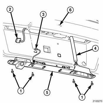
Fig. 7: Backup Camera & Liftgate & Lights
1. Install the camera to the lightbar.
2. Install the camera mounting retainers.
3. Clip the camera cover to the lightbar.
4. Install the retainer to the back of the camera.
5. Connect the liftgate release cable (4) to the lightbar (5).
6. Connect the electrical connectors to the backup camera (2) and the lights (3).
7. Install the lightbar to the tailgate.
8. Install the four retainers (1) holding the lightbar (5) to the liftgate (6).
9. Connect the negative battery cable.
 Diagnosis and Testing
Rear Camera
The hardwired circuits of the Rear View Camera (RVC) and those between the
RVC and the radio receiver may
be diagnosed using conventional diagnostic tools and procedures.
The wiring ...
 Module, satellite video
REMOVAL
1. Disconnect and isolate the negative battery cable.
2. Move the front passenger seat to the most forward position.
Fig. 8: Antenna & Electrical Connectors
3. Disconnect the three ...
See also:
Disassembly
Fig. 241: Tapping Down Reverse Clutch Reaction Plate
- #4 THRUST PLATE (SELECT)
- TAP DOWN REVERSE CLUTCH REACTION PLATE TO REMOVE OR INSTALL SNAP RING
- INPUT SHAFT CLUTCHES RETAINER ASSEMB ...
Description, Operation
DESCRIPTION
Fig. 265: A/C Expansion Valve Description KA
The A/C expansion valve controls the amount of refrigerant entering the A/C
evaporator. The A/C expansion
valve is of a thermostatic exp ...
Installation
Fig. 474: Removing/Installing Valve Body
- VALVE BODY
NOTE: If valve body assembly is being replaced or reconditioned, it is
necessary to
perform the PCM Quick Learn Procedure.
1. ...
