Dodge Journey: Manifold, exhaust, crossover
Removal
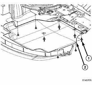
Fig. 287: Belly Pan
- - belly pan fasteners
- - belly pan
1. Remove the belly pan (2).
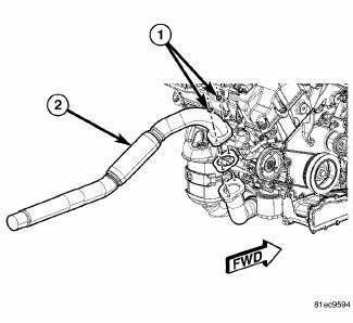
Fig. 288: Exhaust Extension Pipe
2. Remove the fasteners (1), and remove the exhaust extension pipe (2) from the cross under pipe.
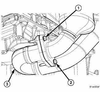
Fig. 289: Exhaust Cross-Under Pipe
3. Remove the rear maniverter-to-cross under pipe fasteners (1) and (2).
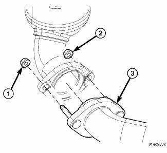
Fig. 290: Front Maniverter-To-Cross Under Fasteners
4. Remove the front maniverter-to-cross under fasteners (1) and (2), and remove the cross under pipe (3).
Installation
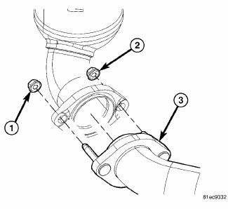
Fig. 291: Front Maniverter-To-Cross Under Fasteners
1. Install the cross under pipe (3). and the front maniverter-to-cross under fasteners (1) and (2). Tighten to 27 Nm (20 ft. lb.).
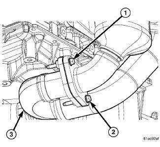
Fig. 292: Exhaust Cross-Under Pipe
2. Install the rear maniverter-to-cross under pipe fasteners (1) and (2). Tighten to 29 Nm (21 ft. lb.).
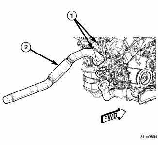
Fig. 293: Exhaust Extension Pipe
3. Install the exhaust extension pipe (2) to the cross under pipe, and install the fasteners (1). Tighten to 27 Nm (20 ft. lb.)
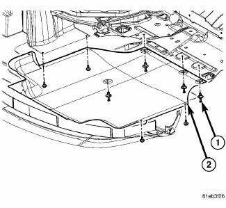
Fig. 294: Belly Pan
- - belly pan fasteners
- - belly pan
4. Install the belly pan (2).
 Manifolds
...
 Manifold, exhaust, front
Removal
1. Disconnect negative battery cable.
2. Remove the engine cover.
Fig. 295: Oxygen Sensors
3. Disconnect and remove oxygen sensors (2) and (4).
Fig. 296: Upper Maniverter Heat Shiel ...
See also:
POWER SUNROOF — IF EQUIPPED
The power sunroof switch is located between the sun
visors on the overhead console.
Power sunroof Switch
WARNING:
• Never leave children in a vehicle with the key in
the ignition switch. Occu ...
Removal
Fig. 431: Identifying Battery Cables
- BATTERY POSITIVE CABLE
- THERMO-WRAP
- BATTERY NEGATIVE CABLE
NOTE: If valve body is replaced or reconditioned, the PCM Quick Learn
Procedure
...
SENTRY KEY
The Sentry Key Immobilizer system prevents unauthorized
vehicle operation by disabling the engine. The
system does not need to be armed or activated. Operation
is automatic, regardless of whether t ...
