
Dodge Journey: Input shaft, transmission
DISASSEMBLY
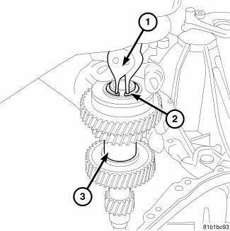
Fig. 175: Snap Ring At Input Shaft
1. Remove the snap ring (2) that retains the input shaft bearing and sixth gear to the shaft.
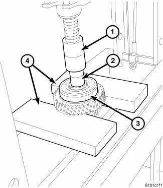
Fig. 176: Press Bearing From Input Shaft
2. Using a press (1) and steel blocks (4) remove sixth gear and the bearing (3) from the shaft.
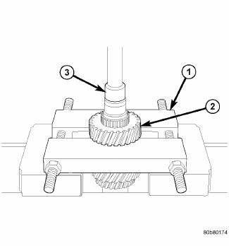
Fig. 177: Input 3rd Gear
3. Using a Press (3) and the Bearing Splitter 1130 (1) remove third gear (2) from shaft.
4. Remove the spacer.
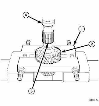
Fig. 178: Fourth Gear Off Input Shaft
5. Using a Press (3) and the Bearing Splitter 1130 (1) remove forth gear (2) from shaft.
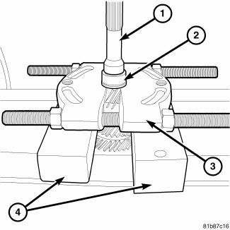
Fig. 179: Input Shaft Bearing Race
6. Using a Press and the Bearing Splitter 1130 (3) remove the input shaft bearing race (2).
ASSEMBLY
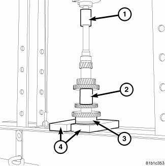
Fig. 180: Bearing On Input Shaft
1. Using a press (1) and steel blocks (4) install third gear and the bearing (3) onto the shaft.
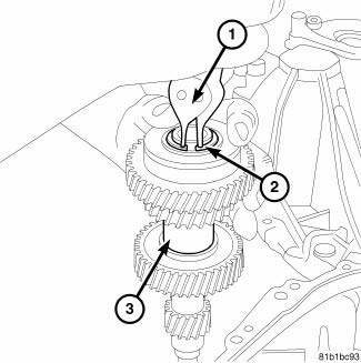
Fig. 181: Snap Ring At Input Shaft
2. Install the new snap ring (2) that retains the input shaft bearing and third gear to the shaft.
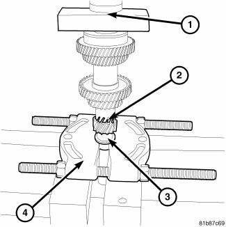
Fig. 182: Install Input Shaft Bearing Race
3. Using Bearing Splitter 1130 (4) and a Press (1) install the input shaft bearing race (3) onto the input shaft (2).
 Fluid
Fluid
STANDARD PROCEDURE
FLUID LEVEL CHECKING
The fluid required for this transaxle is Mopar ATF+4 (Automatic Transmission
Fluid). Use of improper or
substitute fluids can cause shift problems and/or t ...
 Lever, shift
REMOVAL
Fig. 183: Air Cleaner And Inlet Tube
Remove the engine cover.
1. Disconnect battery negative cable.
2. Remove air inlet tube (2) and air cleaner assembly (4).
Fig. 184: Nut Crosso ...
See also:
With intermediate shaft
NOTE: The inner tripod joints are designed with a retention feature
that prevents the
tripod rollers from coming out of the inner joint housing up to a specific
load. If
this feature is o ...
Description, Operation
DESCRIPTION
OPERATION
The following procedure has been established to assist technicians in the
field with enabling and running OBD
II Monitors. The order listed in the following procedur ...
Adjustments
NOTE: Perform all differential bearing preload measurements with the
transfer shaft
and gear removed.
DIFFERENTIAL BEARING PRELOAD ADJUSTMENT USING EXISTING SHIM
Fig. 348: Installing Too ...
