Dodge Journey: Accumulator
DESCRIPTION
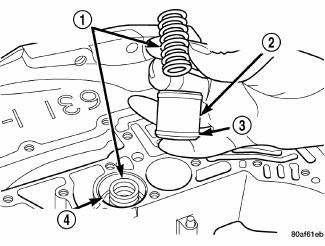
Fig. 238: Identifying Underdrive & Overdrive Accumulators
- - RETURN SPRING
- - UNDERDRIVE CLUTCH ACCUMULATOR
- - SEAL RING (2)
- - OVERDRIVE CLUTCH ACCUMULATOR
The 41TE underdrive, overdrive, low/reverse, and 2/4 clutch hydraulic circuits each contain an accumulator. An accumulator typically consists of a piston (2), seal rings (3) return spring(s) (1) and a cover or plug. The overdrive and underdrive accumulators are located within the transaxle case, and are retained by the valve body.
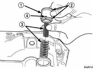
Fig. 239: Removing/Installing Low/Reverse Accumulator Return Springs
- - ACCUMULATOR PISTON
- - SEAL RINGS
- - RETURN SPRINGS
- - (NOTE NOTCH)
The low reverse accumulator (1) is also located within the transaxle case, but the assembly is retained by a cover and a snap-ring.
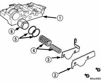
Fig. 240: Identifying 2/4 Accumulator Assembly
- - VALVE BODY
- - RETAINER PLATE
- - DETENT SPRING
- - VALVE BODY
- - RETAINER PLATE
- - DETENT SPRING
The 2/4 accumulator is located in the valve body (1) . It is retained by a cover and retaining screws.
OPERATION
The function of an accumulator is to cushion the application of a frictional clutch element. When pressurized fluid is applied to a clutch circuit, the application force is dampened by fluid collecting in the respective accumulator chamber against the piston and spring(s). The intended result is a smooth, firm clutch application
 Schematics and diagrams
40/41TE - WITH VARIABLE LINE PRESSURE
Fig. 181: Identifying Line Pressure - Park & Neutral
Fig. 182: Identifying Line Pressure - Reverse
Fig. 183: Identifying Line Pressure - First Gear ( ...

See also:
REMOTE SOUND SYSTEM CONTROLS — IF
EQUIPPED
The remote sound system controls are located on the rear
surface of the steering wheel. The left and right-hand
controls are rocker-type switches with a pushbutton in
the center of each switch. Rea ...
ELECTRONIC BRAKE CONTROL SYSTEM
Your vehicle is equipped with an advanced electronic
brake control system commonly referred to as ESP. This
system includes Anti-Lock Brake System (ABS), Brake
Assist System (BAS), Traction Control ...
Cover(s), cylinder head, right
REMOVAL
1. Disconnect negative battery cable.
Fig. 126: Engine Harness Retaining Clips
- Left cylinder head cover engine harness retainers
- Right cylinder head cover engine harness retainer ...
