Dodge Journey: Assembly
Fig. 97: Installing Output Bearing Cups
- - OUTPUT BEARING CUPS
- - WRENCHES
- - INSTALLER - 5050A
CAUTION: The cooler bypass valve must be replaced if transaxle failure has occurred. Do not attempt to reuse or clean old valve.
NOTE: If transaxle is being overhauled (clutch and/or seal replacement), the TCM/PCM Quick Learn procedure must be performed.
1. Install both output bearing cups (1) using Installer 5050A (3).
Fig. 98: Removing/Installing Low/Reverse Piston Retainer-To-Case Gasket
- - GASKET HOLES MUST LINE UP
- - LOW/REVERSE CLUTCH PISTON RETAINER GASKET
2. Install low/reverse piston retainer gasket (2) . Make sure gasket holes line up with case (1).
Fig. 99: Removing/Installing Low/Reverse Piston Retainer
- - LOW/REVERSE CLUTCH PISTON RETAINER
- - GASKET
3. Install low/reverse piston retainer (1) .
Fig. 100: Removing/Installing Low/Reverse Piston Retainer-To-Case Screws
- - LOW/REVERSE CLUTCH PISTON RETAINER
- - SCREWDRIVER
- - TORX-LOC SCREWS
4. Install low/reverse piston retainer-to-case screws (3) and torque to 5 N.m (45 in. lbs.).
Fig. 101: Identifying Low/Reverse Clutch Piston & Bonded Seals
- - LOW/REVERSE CLUTCH PISTON
- - BONDED SEAL
- - BONDED SEAL
NOTE: The Low/Reverse Clutch Piston has bonded seals which are not individually serviceable. Seal replacement requires replacement of the piston assembly.
5. Install low/reverse clutch piston (1) .
Fig. 102: Identifying Guide Bracket Components
6. Use figure Anti-ratching spring (1), guide bracket (2), Split sleeve (3), spacer (4), pawl (5) and stepped spacer (6) as a reference while assembling park guide bracket assembly.
Fig. 103: Identifying Guide Bracket Assembly
- - GUIDE BRACKET
- - ANTIRATCHET SPRING (MUST BE ASSEMBLED AS SHOWN IN ILLUSTRATION)
- - PAWL
7. Assemble park guide bracket assembly .
Fig. 104: Removing/Installing Pivot Shaft & Guide Bracket Assembly
- - ANTIRACHET SPRING
- - GUIDE BRACKET
- - PIVOT SHAFT
- - PAWL
8. Install guide bracket (2) into position and insert pivot shaft (3).
Fig. 105: Installing Anchor Shaft & Plug
- - GUIDE BRACKET ANCHOR SHAFT
- - PIVOT SHAFT
- - ANCHOR SHAFT PLUG
9. Install anchor shaft (1) and plug (3). Make sure guide bracket and split sleeve are in contact with the rear of the transaxle case.
Fig. 106: Removing/Installing Low/Reverse Piston Return Spring
- - LOW/REVERSE PISTON RETURN SPRING
- - PISTON
10. Install low/reverse piston return spring (1) .
Fig. 107: Removing/Installing Low/Reverse Spring Compressor
- - LOW/REVERSE CLUTCH RETURN SPRING
- - SNAP RING (INSTALL AS SHOWN IN ILLUSTRATION)
- - DISC 6057
- - COMPRESSOR 5059-A
- - COMPRESSOR BAR 5058A
11. Install low/reverse spring compressor into position .
Fig. 108: Removing/Installing Remove Snap Ring
- - SNAP RING OPENING MUST BE BETWEEN SPRING LEVERS (AS SHOWN IN ILLUSTRATION)
- - SNAP RING PLIERS
- - DISC 6057
12. Compress low/reverse piston and install snap ring (1) .
Fig. 109: Installing Rear Carrier Bearing Cone
- - ARBOR PRESS RAM
- - INSTALLER 6053
- - NEW BEARING CONE
- - REAR CARRIER ASSEMBLY
13. Install rear carrier bearing cone (3) using Installer 6053 (1).
Fig. 110: Removing/Installing Rear Carrier Assembly
- - REAR CARRIER ASSEMBLY
14. Install rear carrier assembly (1) to transaxle case.
Fig. 111: Installing Output Gear Bearing Cone
- - ARBOR PRESS RAM
- - HANDLE C-4171
- - INSTALLER 5052
- - OUTPUT GEAR
15. Install output gear bearing cone using Installer 5052 (3) .
Fig. 112: Measuring End Play Of Output Gear Bearings
- - GEAR CHECKING PLATE L-4432
- - DIAL INDICATOR
- - SPECIAL SCREWS 6260
- - OUTPUT GEAR
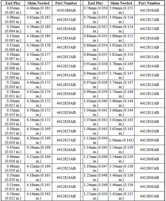
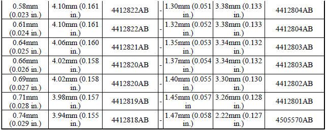
16. OUTPUT GEAR BEARING ADJUSTMENT:
- With output gear removed, install a 4.50 mm (0.177 in.) gauging shim on the rear carrier assembly hub, using grease to hold the shim in place.
- Using Holder 6259, install output gear and bearing assembly. Torque to 271 N.m (200 ft. lbs.).
- Measure bearing end play. Attach Gear Checking Plate L-4432 (1) to the gear.
- Push and pull the gear while rotating back and forth to ensure seating of bearing rollers.
- Using a dial indicator mounted to the transaxle case, measure output gear end play.
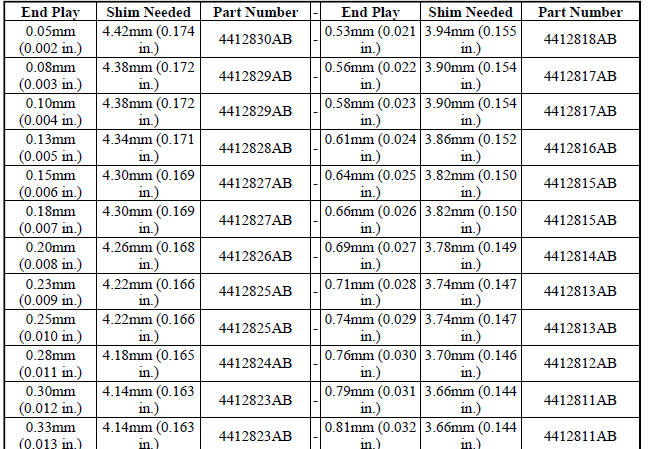
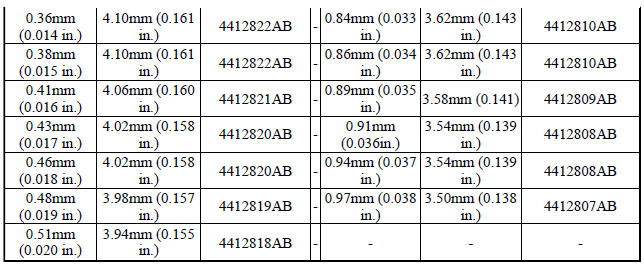
- Refer to OUTPUT GEAR BEARING SHIM CHART for the required shim to obtain proper bearing setting.
- Use Holder 6259 to remove the output gear retaining bolt and washer. To remove the output gear, use Gear Puller L-4407A.
- Remove the gauging shim and install the proper shim determined by the chart. Use grease to hold the shim in place.
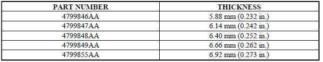
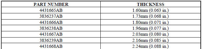
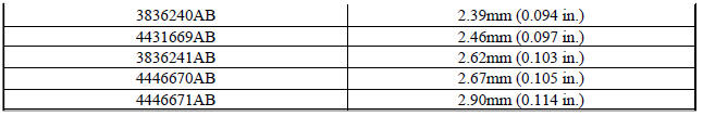
OUTPUT GEAR BEARING SHIM CHART
17. Install the output gear (3) and bearing assembly using Installer 6261 (2).
Fig. 113: Removing/Installing Output Gear Bolt & Washer
- - OUTPUT GEAR
- - BOLT
- - CONED LOCK WASHER
18. Install NEW output gear retaining bolt (2) and washer (3).
Fig. 114: Tightening Output Gear Retaining Bolt
- - OUTPUT GEAR
- - TORQUE WRENCH
- - 200 FT. LBS.
- - HOLDER 6259
19. Using Holder 6259 (4) , torque output gear (1) retaining bolt to 271 N.m (200 ft. lbs.)
Fig. 115: Checking Output Shaft Turning Torque
- - INCH-POUND TORQUE WRENCH
- - OUTPUT GEAR
20. Using an inch pound torque wrench (1) , check output shaft turning torque. Output shaft turning torque should be within 3-8 in. lbs. If the turning torque is too high, install a 0.04 mm (0.0016 in.) thicker shim.
If the turning torque is too low, install a 0.04 mm (0.0016 in.) thinner shim. Repeat until the proper turning torque of 3-8 in. lbs. is obtained.
Fig. 116: Installing Output Gear Stirrup
- - STIRRUP
- - OUTPUT GEAR RETAINING BOLT
21. Install output gear stirrup (1) with serrated side out.
Fig. 117: Removing/Installing Retaining Strap Bolts
- - RETAINING STRAP
- - STIRRUP
- - RETAINING STRAP BOLTS
22. Install retaining strap (1) .
23. Install strap bolts (3) but do not tighten at this time.
Fig. 118: Rotating Stirrup Clockwise Against Flats Of Retaining Bolt
- - RETAINING STRAP
- - STIRRUP
24. Rotate stirrup (2) clockwise against flats of retaining bolt.
Fig. 119: Tightening Stirrup Strap Bolts
- - RETAINING STRAP
- - STIRRUP
25. Torque stirrup strap bolts to 23 N.m (204 in. lbs.) .
Fig. 120: Bending Tabs On Strap Up Against Flats Of Bolts
- - RETAINING STRAP TABS
- - RETAINING STRAP
- - STIRRUP
26. Bend tabs (1) on strap up against flats of bolts.
Fig. 121: Installing Transfer Shaft Bearing Cone
- - INSTALLER 6052
- - NEW BEARING CONE
- - TRANSFER SHAFT
- - ARBOR PRESS RAM
27. Install new transfer shaft bearing cone (2) using Installer 6052 (1).
28. Using Remover/Installer 5049-A (1) , install transfer shaft (2).
Fig. 122: Removing/Installing Transfer Shaft Bearing Snap Ring
- - SNAP RING PLIERS 6051A
- - TRANSFER SHAFT BEARING SNAP RING
- - TRANSFER SHAFT
29. Using Snap Ring Pliers 6051A (1) , install transfer shaft bearing snap ring (2).
Fig. 123: Installing Transfer Shaft Bearing Cup Into Retainer
- - ARBOR PRESS RAM
- - HANDLE C-4171
- - INSTALLER 6061
- - TRANSFER SHAFT BEARING CUP RETAINER
- - USE REMOVED BEARING CUP TO SUPPORT RETAINER
30. Using an arbor press (1) install transfer shaft bearing cup into retainer using Installer 6061(3). Use removed bearing cup to support retainer (4)
Fig. 124: Removing/Installing Bearing Cup Retainer
- - ALIGN INDEXING TAB TO SLOT
- - BEARING CUP RETAINER
31. Install bearing cup retainer (2) to transaxle.
Fig. 125: Installing Transfer Gear Bearing Cone
- - ARBOR PRESS RAM
- - HANDLE C-4171
- - NEW BEARING CONE
- - TRANSFER SHAFT GEAR
- - INSTALLER 5052
32. Install new transfer gear bearing cone (3) to transfer gear (4) using Installer 5052 (5).
Fig. 126: Removing/Installing Transfer Gear Shim (Select)
- - TRANSFER SHAFT GEAR
- - BEARING CUP RETAINER
- - SHIM (SELECT)
33. TRANSFER GEAR BEARING ADJUSTMENT:
- Install a 4.66 mm (0.183 in.) gauging shim on the transfer shaft .
- Install transfer shaft gear using Installer 6261. Using Holder 6259, install transfer shaft gear retaining nut to 271 N.m (200 ft. lbs.).
- Measure end play. Attach Gear Checking Plate L-4432 to the transfer gear.
- Mount a steel ball with grease into the end of the transfer shaft.
- Push and pull the gear while rotating back and forth to ensure seating of the bearing rollers.
- Using a dial indicator, measure transfer shaft end play.
- Refer to TRANSFER SHAFT BEARING SHIM CHART for the required shim combination to obtain the proper bearing setting.
- Use Holder 6259 to remove the retaining nut and washer. Remove the transfer shaft gear using Gear Puller L-4407A.
- Remove the gauging shim and install the proper shim indicated by the chart.
TRANSFER SHAFT BEARING SHIM CHART
34. Install the transfer shaft gear (4) using Installer 6261 (2).
Fig. 127: Tightening Transfer Gear Retaining Nut
- - TRANSFER SHAFT GEAR
- - 200 FT. LBS.
- - TORQUE WRENCH
- - HOLDER 6259
CAUTION: Install a NEW retaining nut, as the original nut MUST NOT be reused.
35. Install the new retaining nut and washer.
36. Using Holder 6259 (4) , torque transfer gear retaining nut to 271 N.m (200 ft. lbs.).
Fig. 128: Removing/Installing Transfer Gear Cover
- - REAR COVER
- - 1/8 INCH BEAD OF MOPAR ATF RTV (MS-GF41)
37. Measure transfer shaft end play. Transfer shaft end play should be within 0.05-0.10 mm (0.002-0.004 in.). If the end play is too high, install a 0.04 mm (0.0016 in.) thicker shim. If the end play is too low, install a 0.04 mm (0.0016 in.) thinner shim. Repeat until 0.05-0.10 mm (0.002-0.004 in.) end play is obtained.
38. Install a bead of Mopar ATF RTV (MS-GF41) (2) to transfer gear cover (1).
Fig. 129: Removing/Installing Transfer Gear Cover-To-Case Bolts
- - REAR COVER BOLTS
- - REAR COVER
- - USE SEALANT ON BOLTS
39. Use sealant on bolts (3) , install transfer gear cover-to-case bolts (1) and torque to 20 N.m (175 in. lbs.) torque.
Fig. 130: Removing/Installing Low/Reverse Clutch Pack
- - CLUTCH PLATES (5)
- - CLUTCH DISCS (5)
40. Install low/reverse clutch pack (1,2) . Leave uppermost disc out until snap ring is installed.
Fig. 131: Removing/Installing Low/Reverse Reaction Plate Snap Ring
- - SCREWDRIVER
- - LOW/REVERSE REACTION PLATE FLAT SNAP RING
- - DO NOT SCRATCH CLUTCH PLATE
41. Install low/reverse reaction plate flat snap ring (2) insure you do not scratch clutch plate (3).
Fig. 132: Removing/Installing Low/Reverse Clutch Disc
- - ONE DISC FROM LOW/REVERSE CLUTCH
42. Install remaining low/reverse clutch disc (1) .
Fig. 133: Removing/Installing Low/Reverse Reaction Plate
- - LOW/REVERSE REACTION PLATE (FLAT SIDE UP)
43. Install low/reverse reaction plate with flat side up (1)
Fig. 134: Installing Tapered Snap Ring
44. Use as a reference while installing tapered snap ring .
Fig. 135: Installing Tapered Snap Ring With Tapered Side Up
- - SCREWDRIVER
- - TAPERED SNAP RING (INSTALL AS SHOWN IN ILLUSTRATION)
45. Install tapered snap ring (with tapered side up) (2)
Fig. 136: Measuring Low/Reverse Clutch Clearance
- - DIAL INDICATOR
- - DIAL INDICATOR TIP TOOL 6268
- - HOOK TOOL
46. Set up dial indicator (1) to measure low/reverse clutch clearance. Press down on clutch pack with finger and zero dial indicator. Low/Reverse clutch pack clearance is 0.89-1.47 mm (0.035-0.058 in.) . Set up indicator and record measurement in four places. Take average of readings and select the proper low/reverse reaction plate to achieve specifications.
LOW/REVERSE REACTION PLATE CHA
47. Install 2/4 clutch pack (1, 2) .
Fig. 137: Identifying Proper Orientation Of 2/4 Clutch Retainer & Return
Spring
- - NOTE POSITION
- - RETURN SPRING
- - 2/4 CLUTCH RETAINER
NOTE: The 2/4 Clutch Piston has bonded seals which are not individually serviceable. Seal replacement requires replacement of the piston assembly.
48. Orient 2/4 clutch return spring to retainer (3) .
Fig. 138: Removing/Installing 2/4 Clutch Retainer
- - 2/4 CLUTCH RETAINER
- - 2/4 CLUTCH RETURN SPRING
49. Install 2/4 clutch retainer to transaxle (1, 2)
Fig. 139: Removing/Installing Snap Ring
- - COMPRESSING TOOL 5058A
- - SCREWDRIVER
- - SNAP RING
- - 2/4 CLUTCH RETAINER
50. Using Compressing Tool 5058A (1) , compress 2/4 clutch return spring just enough to install snap ring (3).
51. Install snap ring.
Fig. 140: Measuring 2/4 Clutch Clearance
- - DIAL INDICATOR
- - HOOK TOOL
- - DIAL INDICATOR TIP 6268
52. Set up dial indicator (1) and measure 2/4 clutch clearance. Press down on clutch pack with finger and zero dial indicator. 2/4 clutch pack clearance is 0.76-2.64 mm (0.030-0.104 in.). Set up indicator and record measurement in four (4) places. Take average of readings. If clearance is outside this range, the clutch is assembled improperly. There is no adjustment for 2/4 clutch clearance.
Fig. 141: Removing/Installing #7 Needle Bearing
- - #7 NEEDLE BEARING
- - REAR SUN GEAR
NOTE: The number seven needle (1) bearing has three anti-reversal tabs and is common with the number five and number two position. The orientation should allow the bearing to seat flat against the rear sun gear. A small amount of petrolatum can be used to hold the bearing to the rear sun gear (2).
Fig. 142: Removing/Installing Rear Sun Gear
- - #7 NEEDLE BEARING
- - REAR SUN GEAR
53. Install rear sun gear (2) and #7 needle bearing (1).
Fig. 143: Removing/Installing Front Carrier/Rear Annulus Assembly
- - #6 NEEDLE BEARING
- - FRONT CARRIER AND REAR ANNULUS ASSEMBLY (TWIST AND PULL OR PUSH TO REMOVE OR INSTALL).
54. Install front carrier/rear annulus assembly (2) and #6 needle bearing (1).
Fig. 144: Removing/Installing Front Sun Gear Assembly
- - FRONT SUN GEAR ASSEMBLY
- - #4 THRUST WASHER (FOUR TABS)
55. Install front sun gear assembly (1) and #4 thrust washer (2).
Fig. 145: Removing/Installing #4 Thrust Plate
- - OVERDRIVE SHAFT ASSEMBLY
- - #4 THRUST PLATE (SELECT)
- - 3 DABS OF PETROLATUM FOR RETENTION
56. Select the thinnest #4 thrust plate thickness (2) and install to input clutch assembly. Use petrolatum to retain (3).
Fig. 146: Verifying Proper Seating Of Input Clutch Assembly
- - INPUT CLUTCH RETAINER
- - INPUT SPEED SENSOR HOLE
- - OIL COOLER FITTINGS
57. Install input clutch assembly into position and verify that it is completely seated by viewing through input speed sensor hole (2) . If view through input speed sensor hole is not as shown in Fig. 146, the input clutch assembly is not seated properly.
Fig. 147: Removing/Installing Oil Pump O-Ring
- - OIL PUMP ASSEMBLY
- - O-RING
58. Remove oil pump o-ring (2) . Be sure to reinstall oil pump o-ring after selecting the proper #4 thrust plate.
59. Install pump and gasket to transmission. Install and torque bolts.
Fig. 148: Measuring Input Shaft End Play
- - END PLAY SOCKET SET 8266A
- - DIAL INDICATOR C-3339A
60. Set up input shaft for measurement with Indicator Set C-3339A (3) and End Play Set 8266A (1) .
61. Measure the input shaft end play with the transaxle in the vertical position. Input shaft end play must be within 0.005 to 0.025 inch. For example, if end play reading is 0.055 inch, select No. 4 Thrust Plate which is 0.071 to 0.074 thick. This should provide an input shaft end play reading of 0.020 inch which is within specifications.
62. Refer to NO. 4 THRUST PLATE CHART to select the proper No. 4 thrust plate.
NO. 4 THRUST PLATE CHART
63. Install input clutch assembly (1) .
Fig. 149: Removing/Installing #1 Caged Needle Bearing
- - #1 CAGED NEEDLE BEARING
- - NOTE: TANGED SIDE OUT
64. Install #1 caged needle bearing (1) note: tanged side out (2)
CAUTION: The cooler bypass valve must be replaced if transaxle failure has occurred. Do not attempt to reuse or clean old valve.
Fig. 150: Removing/Installing Cooler Bypass Valve
- - COOLER BYPASS VALVE
65. Install cooler bypass valve (1) with o-ring end towards rear of case.
Fig. 151: Removing/Installing Oil Pump Gasket
- - PUMP GASKET
66. Install oil pump gasket (1) .
Fig. 152: Installing Oil Pump
- - OIL PUMP
- - GASKET
67. Install oil pump (1) .
Fig. 153: Removing/Installing Oil Pump-To-Case Bolts
- - PUMP ATTACHING BOLTS
- - PUMP HOUSING
68. Install oil pump-to-case bolts (1) and torque to 27 N.m (20 ft. lbs.)
Fig. 154: Installing Low/Reverse Accumulator
- - ACCUMULATOR PISTON
- - SEAL RINGS
- - RETURN SPRINGS
- - (NOTE NOTCH)
69. Install low/reverse accumulator (1) .
Fig. 155: Removing/Installing Low/Reverse Accumulator Plug
- - ADJUSTABLE PLIERS
- - PLUG
70. Install low/reverse accumulator plug (2) .
Fig. 156: Removing/Installing Low/Reverse Accumulator Snap Ring
- - SNAP RING
- - PLUG
71. Install low/reverse accumulator snap ring (1) .
Fig. 157: Installing Underdrive & Overdrive Accumulators
- - OVERDRIVE PISTON AND SPRING
- - UNDERDRIVE PISTON AND SPRING
NOTE: Depending on engine application, some accumulators will have two springs, and others will have one spring. The springs are color-coded for application and year.
72. Install underdrive and overdrive accumulators (1, 2) .
Fig. 158: Removing/Installing Valve Body Assembly
- - VALVE BODY
73. Install valve body (1) to transaxle. Rotate manual valve shaft fully clockwise to ease installation. Make sure park rod rollers are positioned within park guide bracket.
Fig. 159: Removing/Installing Valve Body-To-Case Bolts
- - VALVE BODY ATTACHING BOLTS (18)
- - VALVE BODY
74. Install and torque valve body-to-case bolts (1) to 12 N.m (105 in. lbs.).
Fig. 160: Removing/Installing Oil Filter
- - OIL FILTER
- - O-RING
75. Install oil filter (1) and new o-ring (2).
Fig. 161: Removing/Installing Oil Pan
- - OIL PAN
- - 1/8 INCH BEAD OF MOPAR ATF RTV (MS-GF41)
- - OIL FILTER
76. Apply an 1/8" bead of Mopar ATF RTV (MS-GF41) (2) to oil pan (1) and immediately install to case.
Fig. 162: Identifying Solenoid/Pressure Switch Assembly & Gasket
- - SOLENOID/PRESSURE SWITCH ASSEMBLY
- - GASKET
77. Install oil pan-to-case bolts and torque to 19 N.m (165 in. lbs.).
78. Install solenoid/pressure switch assembly (1) and gasket (2) to case.
Fig. 163: Identifying Solenoid/Pressure Switch Assembly-To-Transaxle Case
Bolts
- - BOLTS
- - SOLENOID AND PRESSURE SWITCH ASSEMBLY
79. Install and tighten solenoid/pressure switch assembly-to-transaxle case bolts (1) to 12 N.m (110 in. lbs.) .
80. Install and torque input and output speed sensors to case to 27 N.m (20 ft. lbs.).
 Disassembly
Fig. 28: Identifying Solenoid/Pressure Switch Assembly & Gasket
- SOLENOID/PRESSURE SWITCH ASSEMBLY
- GASKET
NOTE: If transaxle is being overhauled (clutch and/or seal
replacement ...
 Installation
Fig. 164: Removing/Installing Bellhousing Upper & Lower Bolts
NOTE: If transaxle assembly is being replaced or overhauled (clutch
and/or seal
replacement), it is necessary to perform th ...
See also:
Description, Operation, Diagnosis and Testing
DESCRIPTION
Fig. 1: Accessory Switch Bank Module
Vehicles with the heated seat option can be visually identified by the two
heated seat switches (1) located in the
center stack of the instrumen ...
Cooler, EGR
Description
Fig. 62: EGR COOLER
- EGR COOLER TO EGR VALVE TUBE
- MOUNTING SCREWS
- EGR COOLER MOUNTING SCREW
- MOUNTING SCREW
- EGR COOLER BODY
- EGR COOLER MOUNTING NUT
- EGR COOLE ...
Installation
SATELLITE AUDIO ONLY
NOTE: The antenna cables are integrated into the body wiring
harnesses. New antenna
cables is overlaid on the body wiring harness.
1. Route the cable behind the glove ...
