Dodge Journey: Diagnosis and Testing
STRUT ASSEMBLY
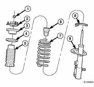
Fig. 80: Strut Assembly (Exploded)
Inspect the strut assembly for the following conditions:
- Inspect for a damaged or broken coil spring (7).
- Inspect for a torn or damaged dust shield (5).
- Inspect for torn or deteriorated spring isolators (4, 8).
- Lift the dust shield and inspect the strut assembly for evidence of fluid running from the upper end of the strut fluid reservoir. (Actual leakage will be a stream of fluid running down the side and dripping off lower end of unit). A slight amount of seepage between the strut shaft and strut shaft seal is not unusual and does not affect performance of the strut assembly.
- Inspect the jounce bumper (6) for signs of damage or deterioration.
- Inspect the clearance between the shock tower and the coil spring. Make sure no fasteners are protruding through the shock tower possibly contacting the coil spring and strut. Because of the minimum clearance in this area, installation of metal fasteners could damage the coil spring coating and lead to a corrosion failure of the spring.
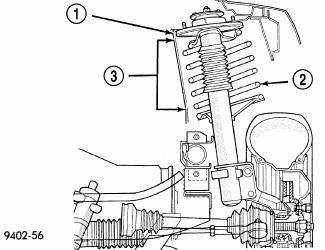
Fig. 81: Shock Tower Area (Typical)
CAUTION: At no time when servicing a vehicle can a sheet metal screw, bolt or other metal fastener be installed into the strut tower (1) to take the place of an original plastic clip. Also, do not drill holes into the front strut tower for the installation of any metal fasteners into the shock tower area indicated (3).
 Description, Operation
DESCRIPTION
A Macpherson type design strut assembly is used in place of the traditional
front suspension upper control arm
and upper ball joint. The bottom of the strut mounts directly to the stee ...
 Removal
1. Remove the engine appearance cover.
Fig. 82: Cowl Top Screen
2. Remove the two push-pins (1) securing the cowl top screen at the ends.
Remove the remaining push-pins
(2). Remove the cowl top ...
See also:
Removal
Fig. 431: Identifying Battery Cables
- BATTERY POSITIVE CABLE
- THERMO-WRAP
- BATTERY NEGATIVE CABLE
NOTE: If valve body is replaced or reconditioned, the PCM Quick Learn
Procedure
...
Clutch air pressure tests
Fig. 6: Identifying Air Pressure Test Plate Tool 6056
- AIR PRESSURE TEST PLATE TOOL 6056
- ACCUMULATORS
Inoperative clutches can be located using a series of tests by substituting
air pr ...
Assembly
HOUSING-AIR DISTRIBUTION
NOTE: LHD model with A/C shown in illustrations. RHD and heater-only
models similar.
Fig. 115: Mode Door Levers-Removal/Installation
1. If removed, install the fo ...
