Dodge Journey: Removal
1. Remove the engine appearance cover.
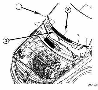
Fig. 82: Cowl Top Screen
2. Remove the two push-pins (1) securing the cowl top screen at the ends. Remove the remaining push-pins (2). Remove the cowl top screen (3).
3. Remove the wiper arms.
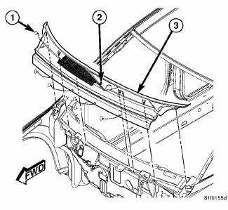
Fig. 83: Cowl Screen
4. Remove the push-pins (1) securing the cowl screen to the wheelhouse brace and cowl. Rotate the screw (2) in the center of the cowl screen 90º clockwise to release the screen. Remove the cowl screen (3).
5. Raise and support the vehicle.
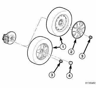
Fig. 84: TIRE AND WHEEL MOUNTING
6. Remove the wheel mounting nuts (3), then the tire and wheel assembly (1).
NOTE: If both strut assemblies are to be removed, mark the strut assemblies right or left and keep the parts separated to avoid mix-up. Not all parts of the strut assembly are interchangeable side-to-side.
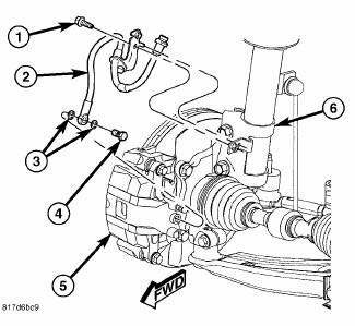
Fig. 85: Brake Hose Mounting To Strut
7. Remove the screw (1) securing the flex hose (2) routing bracket to the strut (6).
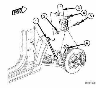
Fig. 86: Strut Mounting To Knuckle
8. While holding the stabilizer bar link (1) stud stationary, remove the nut (4) securing the link to the strut (3).
CAUTION: The strut assembly-to-knuckle attaching bolts (5) are serrated and must not be turned during removal. Hold the bolts stationary in the knuckle while removing the nuts, then tap the bolts out using a pin punch.
9. While holding the bolt heads stationary, remove the two nuts (2) from the bolts (5) attaching the strut (3) to the knuckle (6).
10. Remove the two bolts (5) attaching the strut (3) to the knuckle (6) using a pin punch.
11. Lower the vehicle just enough to open the hood without allowing the tires to touch the floor.
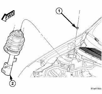
Fig. 87: Strut Upper Mounting Nuts
12. Remove the three nuts (1) attaching the strut assembly (2) upper mount to the strut tower.
13. Remove the strut assembly (2) from the vehicle.
14. For disassembly.
 Diagnosis and Testing
STRUT ASSEMBLY
Fig. 80: Strut Assembly (Exploded)
Inspect the strut assembly for the following conditions:
Inspect for a damaged or broken coil spring (7).
Inspect for a torn or damaged dust ...
 Disassembly
NOTE: The strut assembly must be removed from the vehicle for it to be
disassembled
and assembled.
For the disassembly and assembly of the strut assembly, use strut spring
compressor, tea ...
See also:
Link, stabilizer bar
REMOVAL
1. Raise and support the vehicle.
Fig. 60: TIRE AND WHEEL MOUNTING
2. Remove the wheel mounting nuts (3), then the tire and wheel assembly (1).
Fig. 61: Strut Mounting To Knuckle
3. W ...
Assembly
Fig. 97: Installing Output Bearing Cups
- OUTPUT BEARING CUPS
- WRENCHES
- INSTALLER - 5050A
CAUTION: The cooler bypass valve must be replaced if transaxle
failure has
occur ...
Removal
2.4L
Fig. 45: Locating Knock Sensor
The knock sensor bolts into the side of the cylinder block in front of the
starter under the intake manifold.
1. Disconnect and isolate negative battery ca ...
