Dodge Journey: Duct, instrument panel demister
Removal
WARNING: Disable the airbag system before attempting any steering wheel, steering column or instrument panel component diagnosis or service. Disconnect and isolate the negative battery (ground) cable, then wait two minutes for the airbag system capacitor to discharge before performing further diagnosis or service. This is the only sure way to disable the airbag system. Failure to follow these instructions may result in accidental airbag deployment and possible serious or fatal injury.
NOTE: The left and right demister ducts are serviced with the left and right instrument panel ducts as an assembly.
NOTE: Take the proper precautions to protect the front face of the instrument panel from cosmetic damage while performing this procedure.
NOTE: LHD model shown in illustrations. RHD model similar.

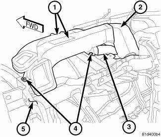
Fig. 81: Driver Instrumental Panel & Demister Duct
1. Remove the instrument panel and place it on a workbench.
2. Remove the outboard instrument panel air outlets.
3. Remove the cover from the instrument panel.
4. Remove the two push-pin retainers (4) that secure the driver side instrument panel and demister duct assembly (1) to the top of the instrument panel support (5).
5. Disconnect the driver side instrument panel and demister duct assembly from the instrument panel center duct (2) and the defroster duct (3) and remove the driver side instrument panel and demister duct assembly.

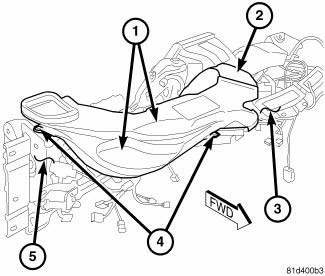
Fig. 82: Pass Instrumental Panel & Demister Duct
6. Remove the two push-pin retainers (4) that secure the passenger side instrument panel and demister duct assembly (1) to the top of the instrument panel support (5).
7. Disconnect the passenger side instrument panel and demister duct assembly from the instrument panel center duct (2) and the defroster duct (3) and remove the passenger side instrument panel and demister duct assembly.
Installation
NOTE: The left and right demister ducts are serviced with the left and right instrument panel ducts as an assembly.
NOTE: Take the proper precautions to protect the front face of the instrument panel from cosmetic damage while performing this procedure.
NOTE: LHD model shown in illustrations. RHD model similar.

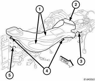
Fig. 83: Pass Instrumental Panel & Demister Duct
1. Position the passenger side instrument panel and demister duct assembly (1) to the instrument panel support (5) and connect the instrument panel and demister duct assembly to the center duct (2) and to the defroster duct (3). Make sure the ducts are fully engaged.
2. Install the two push-pin retainers (4) that secure the passenger side instrument panel and demister duct assembly to the instrument panel support.

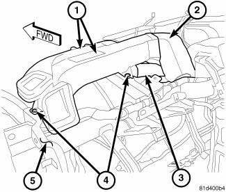
Fig. 84: Driver Instrumental Panel & Demister Duct
3. Position the driver side instrument panel and demister duct assembly (1) to the instrument panel support (5) and connect the instrument panel and demister duct assembly to the center duct (2) and to the defroster duct (3). Make sure the ducts are fully engaged.
4. Install the two push-pin retainers (4) that secure the driver side instrument panel and demister duct assembly to the instrument panel support.
5. Install the cover onto the instrument panel.
6. Install the outboard instrument panel air outlets.
7. Install the instrument panel.
 Duct, instrument panel
Removal
WARNING: Disable the airbag system before attempting any steering
wheel, steering
column or instrument panel component diagnosis or service. Disconnect
and isolate the negati ...
 Filter, particulate air
Description
Fig. 85: Filter-Particulate Air Description
Some models are equipped with a particulate air filter (1) that helps purify
the outside air entering the HVAC
housing. The filter is mou ...
See also:
Removal
WARNING: Review safety precautions and warnings in this part
before performing
this procedure. See Heating and Air Conditioning/Plumbing - Warning
and. Failure to
follow the warnin ...
Seal, crankshaft oil, front
Removal
Fig. 212: Crankshaft Front Oil Seal - Removal
- SPECIAL TOOL 6771
1. Remove crankshaft vibration damper.
2. Install Special Tool 8194, Insert into crankshaft nose. Remove seal us ...
Body, air cleaner
REMOVAL
1. Disconnect negative battery cable.
Fig. 87: Inlet Air Temperature Sensor Electrical Connector
2. Disconnect inlet air temperature sensor electrical connector (3).
3. Disconnect fres ...
