
Dodge Journey: Body, air cleaner
REMOVAL
1. Disconnect negative battery cable.
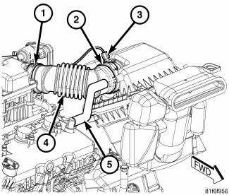
Fig. 87: Inlet Air Temperature Sensor Electrical Connector
2. Disconnect inlet air temperature sensor electrical connector (3).
3. Disconnect fresh air makeup hose (5) from the air filter box.
4. Loosen the clamp (1) from at the throttle body.
5. Remove the air inlet tube (4) from the throttle body.
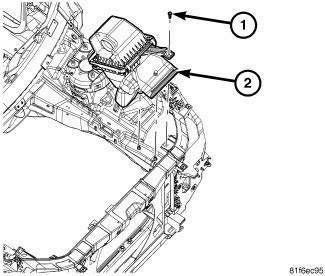
Fig. 88: Retainer From Bracket
6. Remove retainer (1) from bracket.
7. Remove the retainer that secures the air scoop to the top of the radiator core support.
8. Pull air cleaner housing (2) straight up off of locating pins.
INSTALLATION
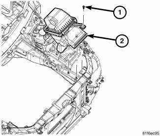
Fig. 89: Retainer From Bracket
1. Install air filter housing (2) straight down on locating pins.
2. Reposition the bracket and install the retainer (1). Tighten the retainer to 5 N.m (44 in. lbs.).
3. Install the push pin that secures the air scoop to the top of the radiator core support.
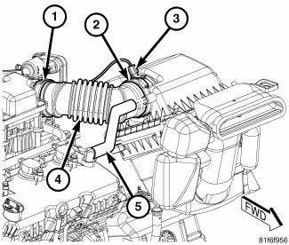
Fig. 90: Inlet Air Temperature Sensor Electrical Connector
4. Install throttle body air inlet tube (4) to the throttle body. Tighten the clamp (1).
5. Connect fresh air makeup hose (5) to the air filter housing
6. Connect inlet air temperature sensor harness connector (3).
7. Connect negative battery cable.
 Air cleaner
REMOVAL
Fig. 85: Air Filter Housing Clips
1. Disengage the air filter housing clips (1).
2. Slide the air filter housing cover (2) forward slightly to disengage tabs
from the bottom of the ai ...
 Cylinder head
...
See also:
FUEL REQUIREMENTS
2.4L Engine
All engines are designed to meet all emissions
regulations and provide excellent
fuel economy and performance when using
high-quality unleaded “regular” gasoline
having an octan ...
Switch, backup lamp
DESCRIPTION
Fig. 43: Backup Lamp Switch
Vehicles equipped with a manual transmission (2) have a normally open,
spring-loaded plunger type backup
lamp switch (1). Vehicles with an optional elect ...
Reinforcement, bumper, front
REMOVAL
Fig. 23: Front Bumper Reinforcement
1. Remove the front fascia. See Removal .
2. Support bumper reinforcement (3) on a suitable lifting device.
3. Mark the position of the bolts (1) ...
