Dodge Journey: Duct, instrument panel
Removal
WARNING: Disable the airbag system before attempting any steering wheel, steering column or instrument panel component diagnosis or service. Disconnect and isolate the negative battery (ground) cable, then wait two minutes for the airbag system capacitor to discharge before performing further diagnosis or service. This is the only sure way to disable the airbag system. Failure to follow these instructions may result in accidental airbag deployment and possible serious or fatal injury.
NOTE: The left and right instrument panel ducts are serviced with the left and right demister ducts as an assembly.
NOTE: Take the proper precautions to protect the front face of the instrument panel from cosmetic damage while performing this procedure.
NOTE: LHD model shown in illustrations. RHD model similar.
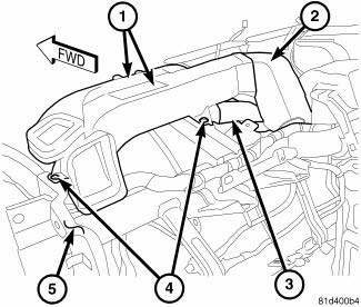
Fig. 75: Driver Instrumental Panel & Demister Duct
1. Remove the instrument panel and place it on a workbench.
2. Remove the outboard instrument panel air outlets. 3. Remove the cover from the instrument panel.
4. Remove the two push-pin retainers (4) that secure the driver side instrument panel and demister duct assembly (1) to the top of the instrument panel support (5).
5. Disconnect the driver side instrument panel and demister duct assembly from the instrument panel center duct (2) and the defroster duct (3) and remove the driver side instrument panel and demister duct assembly.
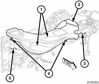
Fig. 76: Pass Instrumental Panel & Demister Duct
6. Remove the two push-pin retainers (4) that secure the passenger side instrument panel and demister duct assembly (1) to the top of the instrument panel support (5).
7. Disconnect the passenger side instrument panel and demister duct assembly from the instrument panel center duct (2) and the defroster duct (3) and remove the passenger side instrument panel and demister duct assembly.
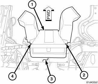
Fig. 77: Center Instrumental Panel Duct
8. Remove the two screws (2 and 4) that secure the instrument panel center duct (1) to the instrument panel support (3) and remove the center duct.
Installation
NOTE: The left and right instrument panel ducts are serviced with the left and right demister ducts as an assembly.
NOTE: Take the proper precautions to protect the front face of the instrument panel from cosmetic damage while performing this procedure.
NOTE: LHD model shown in illustrations. RHD model similar.
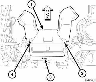
Fig. 78: Center Instrumental Panel Duct
1. Position the instrument panel center duct (3) to the instrument panel support (4) and install the two retaining screws (2 and 4). Tighten the screws to 2.2 N.m (20 in. lbs.).
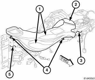
Fig. 79: Pass Instrumental Panel & Demister Duct
2. Position the passenger side instrument panel and demister duct assembly (1) to the instrument panel support (5) and connect the instrument panel and demister duct assembly to the center duct (2) and to the defroster duct (3). Make sure the ducts are fully engaged.
3. Install the two push-pin retainers (4) that secure the passenger side instrument panel and demister duct assembly to the instrument panel support.
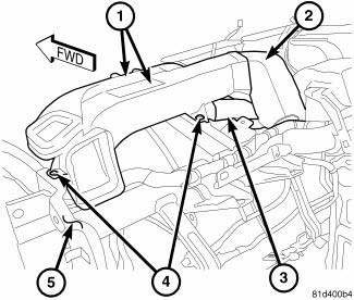
Fig. 80: Driver Instrumental Panel & Demister Duct
4. Position the driver side instrument panel and demister duct assembly (1) to the instrument panel support (5) and connect the instrument panel and demister duct assembly to the center duct (2) and to the defroster duct (3). Make sure the ducts are fully engaged.
5. Install the two push-pin retainers (4) that secure the driver side instrument panel and demister duct assembly to the instrument panel support.
6. Install the cover onto the instrument panel.
7. Install the outboard instrument panel air outlets. 8. Install the instrument panel.
 Installation
NOTE: LHD model shown in illustrations. RHD model similar.
RIGHT FRONT FLOOR DUCT
Fig. 71: Duct-Right Front Floor PM
NOTE: Illustration shown with instrument panel removed for clarity.
...
 Duct, instrument panel demister
Removal
WARNING: Disable the airbag system before attempting any steering
wheel, steering
column or instrument panel component diagnosis or service. Disconnect
and isolate the negati ...
See also:
ELECTRONIC BRAKE CONTROL SYSTEM
Your vehicle is equipped with an advanced electronic
brake control system commonly referred to as ESP. This
system includes Anti-Lock Brake System (ABS), Brake
Assist System (BAS), Traction Control ...
Removal, Installation
REMOVAL
WARNING: To avoid serious or fatal injury on vehicles equipped
with airbags, disable
the Supplemental Restraint System (SRS) before attempting any steering
wheel, steering co ...
Removal
1. Raise and support the vehicle.
2. If equipped, remove the engine belly pan.
3. Remove the rear engine mount.
4. Remove the front engine mount through-bolt.
Fig. 66: Stabilizer Link Mo ...
