Dodge Journey: A/C Performance
The A/C system is designed to provide the passenger compartment with low temperature and low humidity air.
The A/C evaporator, located in the HVAC housing is cooled to temperatures near the freezing point. As warm damp air passes over the fins of the A/C evaporator, the air transfers its heat to the refrigerant in the evaporator coils and the moisture in the air condenses on the evaporator fins. During periods of high heat and humidity, an A/C system will be more effective in the Recirculation mode (max-A/C). With the system in the Recirculation mode, only air from the passenger compartment passes through the A/C evaporator. As the passenger compartment air dehumidifies, the A/C system performance levels rise.
Humidity has an important bearing on the temperature of the air delivered to the interior of the vehicle. It is important to understand the effect that humidity has on the performance of the A/C system. When humidity is high, the A/C evaporator has to perform a double duty. It must lower the air temperature, and it must lower the temperature of the moisture in the air that condenses on the evaporator fins. Condensing the moisture in the air transfers heat energy into the evaporator fins and coils. This reduces the amount of heat the A/C evaporator can absorb from the air. High humidity greatly reduces the ability of the A/C evaporator to lower the temperature of the air.
However, evaporator capacity used to reduce the amount of moisture in the air is not wasted. Wringing some of the moisture out of the air entering the vehicle adds to the comfort of the passengers. Although, an owner may expect too much from their A/C system on humid days. A performance test is the best way to determine whether the system is performing up to design standards. This test also provides valuable clues as to the possible cause of trouble with the A/C system. The ambient air temperature in the location where the vehicle will be tested must be a minimum of 21º C (70º F) for this test. Also the evaporator temperature sensor probe must be a minimum of 16º C (60º F) for this test as well.
A/C PERFORMANCE TEST
WARNING: Refer to the applicable warnings and cautions for this system before performing the following operation. Failure to follow the warnings and cautions may result in possible serious or fatal injury.
CAUTION: The use of an A/C recycling/charging station for purposes of determining the actual charge level of an A/C system is not recommend. Service recycling/charging stations do not reflect the correct amount of refrigerant charge in the A/C system after a single "reclaim" cycle. Tests have shown that it can take two or more "reclaim" cycles to remove all of the refrigerant charge, depending on the equipment being used. Use only the following procedure for determining the proper charge level.
NOTE: When connecting the service equipment coupling to the line fitting, verify that the valve of the coupling is fully closed. This will reduce the amount of effort required to make the connection.
1. Check for diagnostic trouble codes using a scan tool. If no diagnostic trouble codes (DTCs) are found in the A/C-heater control or the powertrain control module (PCM) or engine control module (ECM) (depending on engine application) or the totally integrated power module (TIPM), go to 2. If any DTCs are found, repair as required, then proceed to 2.
2. Connect a tachometer and a manifold gauge set.
NOTE: The ambient air temperature of the vehicle and the location where the vehicle will be tested must be a minimum of 21º C (70º F) before performing this test. Also the evaporator temperature sensor must be a minimum of 18º C (65º F) for this test as well. Place the vehicle in the testing area until the temperature within the vehicle reaches a minimum of 18º C (65º F)
3. Operate the heating-A/C system under the following conditions.
- Engine at normal operating temperature
- Engine at normal idle speed
- Door and windows closed
- Transaxle in Park
- A/C-heater controls set to Recirculation mode, full cool, panel mode, high blower and with A/C compressor engaged. If the A/C compressor does not engage, see the A/C System Diagnosis table
- All panel outlet vanes open and positioned straight rearward
4. Insert a thermometer in the driver side center panel air outlet and operate the A/C system until the thermometer temperature stabilizes or a minimum of 5 minutes.
NOTE: This procedure requires the technician to know what the temperature and relative humidity is at the time of the test. The temperature must be combined with the relative humidity to calculate the apparent ambient temperature, when the temperatures are above 21º C (70º F). Use the current ambient temperature and the relative humidity in your location.
This information can be obtained from multiple sources, such as the internet or local news media.
5. With the A/C compressor clutch engaged, compare the air temperature at the center panel outlet and the compressor discharge pressure (high side) to the A/C Performance Temperature and Pressure chart.
A/C PERFORMANCE TEMPERATURE AND PRESSURE
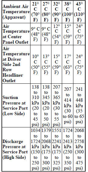
6. If the air outlet temperature fails to meet the specifications in the A/C Performance Temperature and Pressure chart, or if the compressor discharge pressure is high.
A/C SYSTEM DIAGNOSIS
|
CONDITION |
POSSIBLE CAUSES | CORRECTION |
| Rapid A/C compressor clutch cycling with poor panel outlet temperatures (fixed displacement compressors only). | 1. Low refrigerant system charge. | 1. See REFRIGERANT SYSTEM LEAKS. Test the refrigerant system for leaks. Repair, evacuate and charge the refrigerant system, if required. |
| Equal low and high side pressures | 1. No refrigerant in the refrigerant system. | 1. See REFRIGERANT SYSTEM LEAKS. Test the refrigerant system for leaks. Repair, evacuate and charge the refrigerant system, if required. |
| 2. Inoperative A/C compressor or clutch (depending on compressor application). | 2. See COMPRESSOR, A/C. Test the compressor and/or clutch and replace, if required. | |
| 3. Improperly installed or inoperative evaporator temperature sensor. | 3. See SENSOR, Evaporator Temperature. Correctly install or test the sensor and replace, if required. | |
| 4. Improperly installed or inoperative A/C pressure transducer. | 4. See TRANSDUCER, A/C Pressure.
Test the transducer and replace, if required. |
|
| 5. Inoperative A/C-heater control, totally integrated power module (TIPM) or PCM/ECM (depending on engine application). | 5. See the appropriate Electrical Diagnostic Procedures for testing of the A/C-heater control, TIPM or PCM/ECM. Test the module and replace, if required. | |
| Normal refrigerant pressures, but A/C Performance Test air temperatures at center panel outlet are too high. | 1. Excessive refrigerant oil in system. | 1. See REFRIGERANT OIL LEVEL.
Recover the refrigerant from the refrigerant system and inspect the refrigerant oil content. Restore the refrigerant oil to the proper level, if required. |
| 2. Blend door actuator(s) improperly installed or inoperative | 2. See ACTUATOR, Blend Door, Front. Inspect the actuator(s) for proper operation. Replace the actuator as required. | |
| 3. Blend-air door(s) inoperative or sealing improperly. | 3. See HOUSING, HVAC. Inspect the blend-air door(s) for proper operation and sealing. Repair if required. | |
| The low side pressure is normal or slightly low, and the high side pressure is too low. | 1. Low refrigerant system charge. | 1. See REFRIGERANT SYSTEM LEAKS. Test the refrigerant system for leaks. Repair, evacuate and charge the refrigerant system, if required. |
| 2. Refrigerant flow through the A/C evaporator is restricted. | 2. See EVAPORATOR, A/C, Front.
Replace the restricted A/C evaporator, if required. |
|
| 3. Restricted refrigerant flow through the refrigerant lines. | 3. See Plumbing, Front. Inspect the refrigerant lines for kinks, tight bends or improper routing. Correct the routing or replace the refrigerant line if required. | |
| 4. Inoperative A/C compressor. | 4. See COMPRESSOR, A/C. Replace the compressor, if required. | |
| The low side pressure is normal or slightly high, and the high side pressure is too high. | 1. Inoperative radiator cooling fan. | 1. See COOLING . Test the radiator cooling fan and replace, if required. |
| 2. A/C condenser air flow restricted. | 2. See CONDENSER, A/C. Check the A/C condenser for damaged fins, foreign objects obstructing air flow through the condenser fins and missing or improperly installed air seals. Clean, repair or replace components as required. | |
| 3. Refrigerant flow through the A/C receiver/drier is restricted. | 3. See DRIER, A/C Receiver. Replace the restricted A/C receiver/drier, if required. | |
| 4. Restricted refrigerant flow through the refrigerant lines. | 4. See Plumbing, Front. Inspect the refrigerant lines for kinks, tight bends or improper routing. Correct the routing or replace the refrigerant line if required. | |
| 5. Refrigerant system overcharged. | 5. See REFRIGERANT SYSTEM CHARGE. Recover the refrigerant from the refrigerant system. Charge the refrigerant system to the proper level, if required. | |
| 6. Air in the refrigerant system. | 6. See REFRIGERANT SYSTEM LEAKS. Test the refrigerant system for leaks. Repair, evacuate and charge the refrigerant system, if required. | |
| 7. Engine overheating. | 7. See COOLING . Test the engine cooling system and repair, if required. | |
| The low side pressure is too high, and the high side pressure is too low. | 1. Accessory drive belt slipping. | 1. See COOLING . Inspect the accessory drive belt condition and tension. Replace the accessory drive belt or tensioner, if required. |
| 2. Inoperative A/C expansion valve. | 2. See VALVE, A/C Expansion.
Replace the valve, if required. |
|
| 3. Inoperative A/C compressor. | 3. See COMPRESSOR, A/C. Replace the compressor, if required. | |
| The low side pressure is too low, and the high side pressure is too high. | 1. Restricted refrigerant flow through the refrigerant lines. | 1. See LINE, A/C Liquid, LINE, A/C
Suction and LINE, A/C Discharge.
Inspect the refrigerant lines for kinks, tight bends or improper routing. Correct the routing or replace the refrigerant line, if required. |
| 2. Restricted refrigerant flow through the A/C expansion valve. | 2. See VALVE, A/C Expansion.
Replace the valve, if required. |
|
| 3. Restricted refrigerant flow through the A/C condenser. | 3. See CONDENSER, A/C. Replace the restricted condenser, if required. |

 Heater performance
Before performing the following tests, see COOLING for the procedures to
check the engine coolant level and
flow, engine coolant reserve/recovery system operation, accessory drive belt
condition ...
See also:
VIDEO ENTERTAINMENT SYSTEM (VES)™ — IF EQUIPPED
The optional Video Entertainment System (VES)™ includes
the following components for rear seat entertainment:
• A diagonal 8 in (20 cm) Liquid Crystal Display (LCD)
screen integrated into the c ...
DRIVING ON SLIPPERY SURFACES
Acceleration
Rapid acceleration on snow covered, wet, or other slippery
surfaces may cause the front wheels to pull erratically
to the right or left. This phenomenon occurs when
there is a differe ...
Description, Standard procedure
DESCRIPTION
Fig. 331: Identifying Timing Drive System Components
The timing drive system has been designed to provide quiet performance and
reliability to support a NON freewheeling
engine. The ...
