
Dodge Journey: Cover, structural dust
Removal
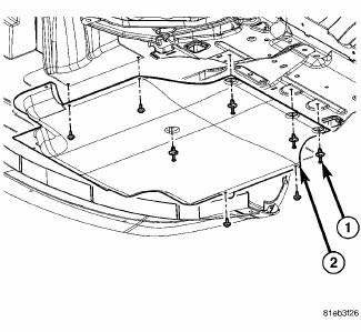
Fig. 172: Belly Pan
1. Raise and secure the vehicle on a hoist.
2. Remove the belly pan (2), if equipped.
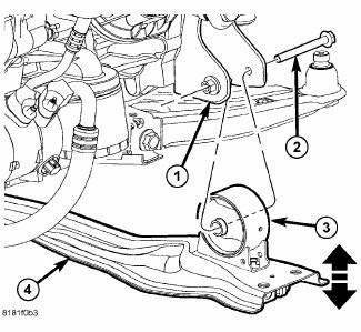
Fig. 173: Front Engine Mount Through Bolt
3. Remove the fore/aft crossmember (4).
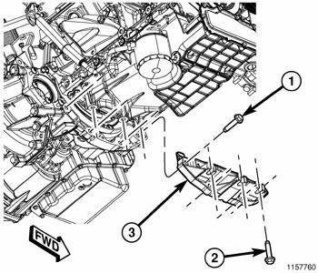
Fig. 174: Structural Collar
4. Remove three bolts (2) attaching the structural collar (3) to the oil pan.
5. Remove four bolts (1) and the structural collar (3) from the transmission.
Installation
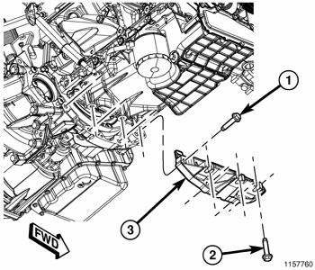
Fig. 175: Structural Collar
CAUTION: The collar must be tightened using this service procedure, as damage to transaxle case and/or oil pan may occur.
1. Position the structural collar (3) on the engine and transaxle.
2. Finger tighten all bolts (1) and (2).
NOTE: Make sure that structural collar (3) is flush with the oil pan and the transmission bell housing.
3. Install the vertical collar bolts (2) to the oil pan, pre-torque bolts to 1.1 N.m (10 in. lbs.).
4. Install the horizontal collar bolts (1) to the transmission and tighten to 55 N.m (40 ft. lbs.).
5. Starting with the center vertical bolts and working outward, final torque all bolts to 55 N.m (40 ft. lbs.).
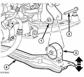
Fig. 176: Front Engine Mount Through Bolt
6. Install the fore/aft crossmember (4).
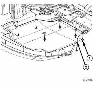
Fig. 177: Belly Pan
7. Install the belly pan (2), if equipped.
8. Lower the vehicle.
 Bearing(s), crankshaft, main
Standard Procedure
CRANKSHAFT MAIN BEARING FITTING
Fig. 169: Cylinder Block Main Bore Grade Marking
The grade marks for the cylinder block main bearing bore grade is located on
the pan rail jus ...
 Crankshaft
Description
The crankshaft is constructed of a forged micro alloy steel. The six throw,
nine counterweight crankshaft is
supported by four select fit main bearings with the number three serving as ...
See also:
VEHICLE IDENTIFICATION NUMBER
The Vehicle Identification Number (VIN) is on the left
front corner of the instrument panel and is visible from
outside of the vehicle through the windshield. This
number also appears on the Automo ...
With intermediate shaft
NOTE: The inner tripod joints are designed with a retention feature
that prevents the
tripod rollers from coming out of the inner joint housing up to a specific
load. If
this feature is o ...
Rod, piston and connecting
Description
Fig. 206: Piston & Connecting Rod
- "F" TOWARD FRONT OF ENGINE
- RING COMPRESSOR
- SPECIAL TOOL 8189
- OIL SQUIRT HOLE
The pistons (1) are made of a high stre ...
