Dodge Journey: Installation
Fig. 40: Seal Protector
- - HALFSHAFT
- - SEAL PROTECTOR
1. Install halfshaft to hub/bearing assembly. Install hub nut and washer but do not tighten at this time.
2. Using Seal Protector 9099 (2) , install halfshaft (1) to differential assembly. Clean tool and seal area to prevent debris intrusion.
Fig. 41: Module Mounting Bolt
- - BOLT
- - DRIVELINE MODULE
3. Raise driveline module into position. Install module mounting bolt (1) .
Fig. 42: Module Mounting Bolts
- - BOLT (2)
- - DRIVELINE MODULE
4. Install remaining two module mounting bolts (2) .
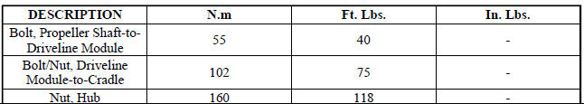
5. Torque module-to-cradle bolts to 102 N.m (75 ft. lbs.) 6. Torque the halfshaft/hub nut to 160 N.m (118 ft.lbs.).
7. Install wheel center cap.
8. Check and adjust differential fluid level.
SPECIFICATIONS

SPECIAL TOOLS
Fig. 43: Protector, 9099
 Removal
Fig. 35: Removing/Installing Halfshaft Nut
NOTE: Rear suspension and drivetrain design require this procedure to
be performed
on a "drive-on" hoist, as the front and rear suspensi ...
 Intermediate shaft, gas
REMOVAL
2.4L
1. Remove the right half shaft.
Fig. 44: Intermediate Shaft - 2.4L
2. Remove the three intermediate shaft bolts (1).
3. Remove the intermediate shaft (2).
2.7L
1. Remove the r ...
See also:
OCCUPANT RESTRAINTS
Some of the most important safety features in your
vehicle are the restraint systems:
• Three-point lap and shoulder belts for all seating
positions.
• Advanced Front Airbags for driver and fr ...
Description
Fig. 142: Instrument Panel Outlets
There are two defroster air outlets (1) in the defroster grille (2) located
at the top of the instrument panel. The
airflow from the defroster outlets are dire ...
Damper, vibration
Removal
Fig. 196: Vibration Damper - Removal
- SPECIAL TOOL 8454 PULLER
- SPECIAL TOOL 8194 INSERT
1. Disconnect negative battery cable.
2. Remove right front wheel and belt splash shie ...
