Dodge Journey: Installation
NOTE: Perform 1 through 5 on each side of the vehicle to complete pad set installation, then proceed to 6.
NOTE: Make sure that the audible wear indicator (if equipped) is placed toward the top when the inboard brake pad is installed on each side of the vehicle.
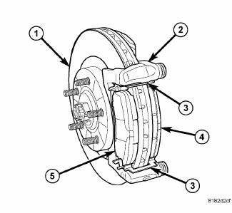
Fig. 121: FRONT BRAKE PADS
NOTE: If the brake pads have a protective paper on the rear face of the brake pad plate, it must be removed before pad installation.
1. Place the brake pads (4, 5) in the abutment shims (3) clipped into the disc brake caliper adapter bracket (2) as shown. Place the pad with the wear indicator (if equipped) attached on the inboard side (2).
2. Completely retract the caliper piston back into the bore of the caliper. Fig. 122:
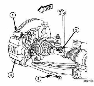
Fig. 122: CALIPER GUIDE PIN BOLTS
CAUTION: Use care when installing the caliper (4) onto the adapter bracket (1) to avoid damaging the boots.
3. Install the disc brake caliper over the brake pads on the brake caliper adapter bracket.
CAUTION: When removing or installing a caliper guide pin bolt, it is necessary to hold the guide pin stationary while turning the bolt. Hold the guide pin stationary using a wrench placed upon the pin's hex-shaped head.
4. Align the caliper guide pin bolt holes with the adapter bracket. Install the upper (2) and lower (3) caliper guide pin bolts. Tighten the guide pin bolts to 35 N.m (26 ft. lbs.).
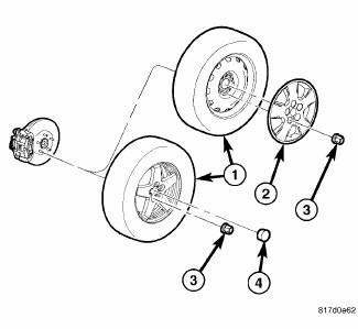
Fig. 123: TIRE AND WHEEL MOUNTING
5. Install tire and wheel assembly (1). Install and tighten wheel mounting nuts (3) to 135 N.m (100 ft. lbs.).
6. Lower the vehicle.
7. Pump the brake pedal several times before moving the vehicle to set the pads to the brake rotor.
8. Check and adjust the brake fluid level in the reservoir as necessary.
9. Road test the vehicle and make several stops to wear off any foreign material on the brakes and to seat the brake pads.
 Removal
1. Raise and support the vehicle.
NOTE: Perform 2 through 5 on each side of the vehicle to complete pad
set
removal.
Fig. 117: TIRE AND WHEEL MOUNTING
2. Remove the wheel mounting nuts ...

See also:
Unit, heater
DESCRIPTION
Fig. 323: Positive Temperature Coefficient Heater - Description
NOTE: LHD model shown. RHD model similar.
An electric positive temperature coefficient (PTC) heater unit (1) is us ...
Without intermediate shaft
NOTE: Never grasp the halfshaft assembly by the inner or outer boots
doing so may
damage to the boot.
NOTE: The inner tripod joints are designed with a retention feature that
prevents t ...
Electrical
SWITCH, BRAKE FLUID LEVEL
Description
The brake fluid level switch (2) is mounted through the center of the fluid
reservoir. The switch can be serviced
separately from the master cylinder fluid r ...
