
Dodge Journey: Lamp, center high mounted stop
REMOVAL
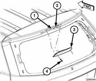
Fig. 5: Center High Mounted Stop Lamp
1. Disconnect and isolate the battery negative cable.
2. Remove the two screws (4) that secure the Center High Mounted Stop Lamp (CHMSL) (3) to the liftgate header panel (1).
3. Pull the CHMSL away from the liftgate far enough to access and disconnect the connector (2) of the liftgate wire harness (1) from the connector receptacle on the back of the lamp.
4. Remove the CHMSL from the liftgate.
INSTALLATION
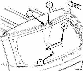
Fig. 6: Center High Mounted Stop Lamp
1. Check to be certain that the two U-nuts in the Center High Mounted Stop Lamp (CHMSL) opening of the liftgate header panel are properly installed and in good condition.
2. Position the CHMSL (3) near the opening in the liftgate header panel.
3. Reconnect the connector (2) of the liftgate wire harness (1) to the connector receptacle on the back of the lamp.
4. Position the CHMSL into the liftgate header opening.
5. Install and tighten the two screws (4) that secure the CHMSL to the liftgate header panel. Tighten the screws to 1.5 N.m (15 in. lbs.).
6. Reconnect the battery negative cable.
 Cam, turn signal cancel
DESCRIPTION
The turn signal cancel cam is concealed within the clockspring case on the
steering column. The turn signal
cancel cam consists of integral eccentrics on the outer circumference of the ...
 Lamp, fog, front
REMOVAL
BULB
CAUTION: Do not contaminate the bulb glass by touching it with
your fingers or by
allowing it to contact other oily surfaces. Shortened bulb life will
result.
...
See also:
Module, heated seat
DESCRIPTION
Fig. 35: Locating Heated Seat Module
The heated seat module (2) is located under the driver front seat. It has a
single electrical connector (1) and a
push pin style retainer that s ...
Amplifier
DESCRIPTION
The optional premium speaker system includes a separate audio power
amplifier. The amplifier is an eight
channel unit. The amplifier is located behind the right cowl trim panel.
OPERA ...
Fascia, rear
REMOVAL
Fig. 15: Push Pins
1. Open the hatch.
2. Remove the 6 pushpins (1) securing the fascia (2).
Fig. 16: Rivets
3. Remove the rivets (2) and the Torx screw (3) around the wheel well for ...
