Dodge Journey: Removal
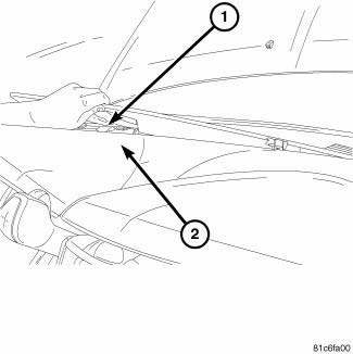
Fig. 393: Removing/Installing Defroster Cover
1. Disconnect the negative battery cable.
2. Using a trim stick remove the defroster cover (1).
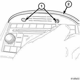
Fig. 394: Removing/Installing Screws At Center Stack Cover
3. Remove the screws (1) at the center stack cover (2).
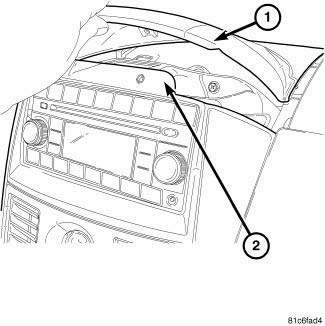
Fig. 395: Removing/Installing Center Stack Cover
4. Remove the center stack cover (1).
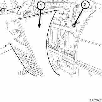
Fig. 396: Pulling Center Stack Back
5. Pull center stack (1) back.
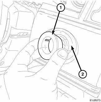
Fig. 397: Removing/Installing Ignition Switch Bezel
6. Remove the ignition switch bezel (1) from I/P cover (2).
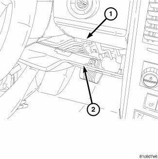
Fig. 398: Identifying Knee Blocker
7. Remove the knee blocker (2).
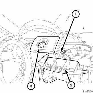
Fig. 399: Removing/Installing I/P Cover
8. Remove the I/P cover (3) (if equipped).
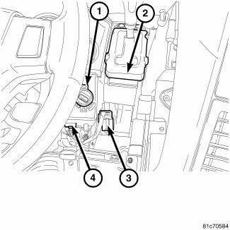
Fig. 400: Identifying Electrical Connectors At WIN & Shifter
9. Remove the cluster bezel.
10. Remove the shift knob.
11. Unplug the electrical connectors (3, 4) at the WIN (1) and the shifter (2).
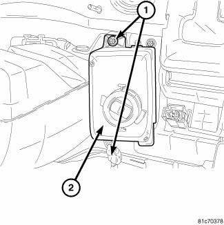
Fig. 401: Removing/Installing Screws At Win
12. Remove the screws (1) at the WIN (2).
13. Remove the WIN to gain access to the lower shifter bolts.
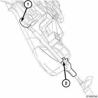
Fig. 402: Identifying Shift Cable At Shifter
NOTE: Ensure the lock tab at the shifter housing (2) is depressed before pulling the cable from the shifter housing.
14. Remove the shift cable (1, 2) at the shifter.
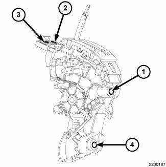
Fig. 403: Identifying Shifter Mounting Bolts
15. Remove the shifter mounting bolts 1 thru 4.
16. Remove the shifter.

 Installation
Fig. 404: Identifying Shifter Mounting Bolts
1. Install the shifter mounting bolts and tighten to 20 N.m (15 ft. lbs.) in
the proper sequence as indicated on
drawing.
Fig. 405: Identifying Sh ...
See also:
Disassembly, Assembly
DISASSEMBLY
NOTE: If the reservoir is being replaced, the new reservoir will come
with a brake fluid
level switch installed. The old fluid switch does not need to be transferred
from
the ...
Installation
CAUTION: Be certain to adjust the refrigerant oil level when
servicing the A/C
refrigerant system. Failure to properly adjust the refrigerant
oil level will prevent the A/C system fro ...
ELECTRONIC BRAKE CONTROL SYSTEM
Your vehicle is equipped with an advanced electronic
brake control system commonly referred to as ESP. This
system includes Anti-Lock Brake System (ABS), Brake
Assist System (BAS), Traction Control ...
