Dodge Journey: Wheel alignment
PRE-WHEEL ALIGNMENT INSPECTION
Before any attempt is made to change or correct the wheel alignment, the following inspection and necessary corrections must be made to the vehicle to ensure proper alignment.
1. Verify the fuel tank is full of fuel. If the fuel tank is not full, the reduction in weight will affect the curb height of the vehicle and the alignment specifications.
2. The passenger and luggage compartments of the vehicle should be free of any load that is not factory equipment.
3. Check the tires on the vehicle. The tires are to be inflated to the recommended air pressure. All tires must be the same size and in good condition with approximately the same tread wear.
4. Check the front tire and wheel assemblies for excessive radial runout.
5. Inspect all suspension component fasteners for looseness and proper torque.
6. Inspect the lower front ball joints and all steering linkage for looseness and any sign of wear or damage.
7. Inspect the rubber bushings on all the suspension components for signs of wear or deterioration. If any bushings show signs of wear or deterioration, they should be replaced prior to aligning the vehicle.
8. Check vehicle curb height to verify it is within specifications.
WHEEL ALIGNMENT SETUP
1. Position the vehicle on an alignment rack.
2. Install all required alignment equipment on the vehicle, per the alignment equipment manufacturer's instructions. On this vehicle, a four-wheel alignment is recommended.
NOTE: Prior to reading the vehicle's alignment readouts, the front and rear of vehicle should be jounced. Induce jounce (rear first, then front) by grasping the center of the bumper and jouncing each end of vehicle an equal number of times. The bumper should always be released when vehicle is at the bottom of the jounce cycle.
3. Read the vehicle's current front and rear alignment settings. Compare the vehicle's current alignment settings to the vehicle specifications for camber, caster and toe-in.
REAR CAMBER
Rear camber settings on this vehicle are determined at the time the vehicle is designed, by the location of the vehicle's suspension components. This is referred to as Net Build. The result is no required adjustment of camber after the vehicle is built or when servicing the suspension components. Thus, when performing a wheel alignment, rear camber is not considered an adjustable angle.
CAUTION: Do not attempt to adjust the vehicle's wheel alignment by heating or bending any of the suspension components.
FRONT CAMBER AND CASTER
Front camber and caster settings on this vehicle are determined at the time the vehicle is designed, by the location of the vehicle's suspension components. This is referred to as Net Build. The result is no required adjustment of camber and caster after the vehicle is built or when servicing the suspension components. Thus, when performing a wheel alignment, caster and camber are not normally considered adjustable angles but some adjustment can be made. Camber and caster should be checked to ensure they meet vehicle specifications.
If individual front camber or caster is found not to meet alignment specifications, each can be adjusted by shifting the front crossmember or by using an available service adjustment bolt package. If an adjustment bolt package installation is necessary, inspect the suspension components for any signs of damage or bending first.
CAUTION: Do not attempt to adjust the vehicle's wheel alignment by heating or bending any of the suspension components.
ADJUSTMENT BY SHIFTING CROSSMEMBER
CAUTION: Always use care when shifting crossmember to avoid damaging other components on the vehicle.
1. Loosen the four bolts fastening the front crossmember to the frame just enough to allow movement of the crossmember.
2. Loosen the bolts fastening the fore/aft crossmember to the frame just enough to allow movement of the crossmember.
CAUTION: When shifting the front crossmember, keep in mind that the front and rear engine mounts are attached to the front crossmember and fore/aft crossmember and should be inspected following the crossmember shift to make sure they are properly aligned.
3. Shift front crossmember as necessary (See following tables) to bring camber or caster into specifications.
When shifting crossmember, use care not to move other angles (camber or caster) that are within specifications, out of specifications.
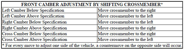
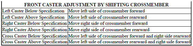
4. Tighten all previously loosened fasteners (bolts) securing the crossmember to the vehicle to specifications. 5. Jounce the rear, then front of the vehicle an equal amount of times.
6. Measure camber and caster. If camber and caster are within specifications, proceed to TOETOE. If camber cannot be brought into specifications, perform CAMBER ADJUSTMENT BOLT PACKAGE INSTALLATION.
CAMBER ADJUSTMENT BOLT PACKAGE INSTALLATION
1. Raise the vehicle until its tires are not supporting the weight of the vehicle.
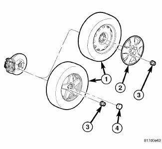
Fig. 111: TIRE AND WHEEL MOUNTING
2. Remove the wheel mounting nuts (3), then the front tire and wheel assembly (1).
CAUTION: The strut clevis-to-knuckle attaching bolt shanks are serrated and must not be turned during removal. Remove the nuts while holding the bolts stationary, then tap the bolts out using a punch.
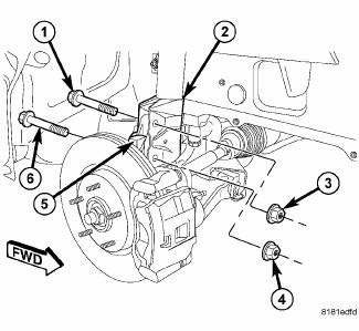
Fig. 112: Strut Clevis Bracket
3. Remove the original nuts (3, 4) and upper (1) and lower (6) bolts attaching the strut clevis bracket (2) to the knuckle (5).
4. Separate the knuckle (5) from the strut clevis bracket (2) and position knuckle so it is out of the way of the strut. Use care not to overextend the brake flex hose or axle half shaft.
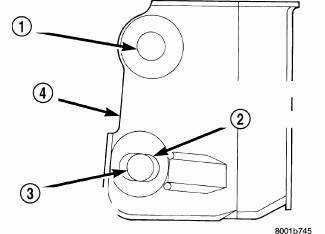
Fig. 113: Strut Clevis Bracket Bolt Hole Grinding Area
CAUTION: When slotting the bottom mounting hole (3) on the strut clevis bracket (4), do not enlarge the hole beyond the indentations (2) on the sides of the strut clevis bracket.
5. Using an appropriate grinder and grinding wheel, slot the bottom hole (3) in both sides of the strut clevis bracket (4).
CAUTION: After slotting the strut clevis bracket hole, do not install the original attaching bolts. Only the service package bolts and dog bone washers must be used to attach the knuckle to the strut once the mounting hole is slotted.
6. Position the strut clevis bracket in line with the upper end of the knuckle, aligning the mounting holes.
Install the two service package bolts. Be sure to place the bolt with the eccentric cam in the bottom (slotted) hole on strut clevis bracket.
7. Install the dog bone washers provided in the service package and nuts on the replacement bolts. Tighten each nut just enough to hold the knuckle in position while adjusting camber, but still allows the knuckle to move in the clevis bracket.

Fig. 114: TIRE AND WHEEL MOUNTING
8. Install the tire and wheel assembly (1). Install and tighten the wheel mounting nuts (3) to 135 N.m (100 ft. lbs.).
9. Perform the above procedure to opposite side strut as required.
10. Lower the vehicle and jounce the front and rear of the vehicle.
11. Adjust the front camber to the preferred setting using the cam bolt in the lower mounting hole. Once camber is set to specifications, tighten the upper and lower strut service package bolt nuts to 140 N.m (103 ft. lbs.). Again jounce the front and rear of the vehicle, then verify the camber settings.
12. Once camber is within specifications, adjust toe to meet the preferred specification setting. Refer to TOE within this wheel alignment service procedure.
 Curb height measurement
The wheel alignment is to be checked and all alignment adjustments made with
the vehicle at its required curb
height specification.
Vehicle height is to be checked with the vehicle on a flat, le ...
 Toe
Toe
Fig. 115: Steering Wheel Holding Tool
1. Center the steering wheel and lock it in place using a steering wheel
clamp.
NOTE: When setting toe, make sure to set rear toe to the preferred
spe ...
See also:
Converter, catalytic
DESCRIPTION
WARNING: The normal operating temperature of the exhaust system is
very high.
Therefore, never work around or attempt to service any part of the
exhaust system until it ...
VEHICLE SECURITY ALARM — IF EQUIPPED
The Vehicle Security Alarm (VSA) system monitors the
vehicle doors and liftgate for unauthorized entry. If
something triggers the alarm, the system will sound the
horn intermittently, flash the hea ...
Description
Fig. 1: 2.7 Liter Engine
The 2.7 Liter (167 Cubic Inches) 60 degree V6 engine is a double overhead
camshaft design with hydraulic
lifters and four valves per cylinder. The engine does not have p ...
