Dodge Journey: Curb height measurement
The wheel alignment is to be checked and all alignment adjustments made with the vehicle at its required curb height specification.
Vehicle height is to be checked with the vehicle on a flat, level surface, preferably a vehicle alignment rack. The tires are to be inflated to the recommended pressure. All tires are to be the same size as standard equipment.
Vehicle height is checked with the fuel tank full of fuel, and no passenger or luggage compartment load.
Vehicle height is not adjustable. If the measurement is not within specifications, inspect the vehicle for bent or weak suspension components. Compare the parts tag on the suspect coil spring(s) to the parts book and the vehicle sales code, checking for a match. Once removed from the vehicle, compare the coil spring height to a correct new or known good coil spring. The heights should vary if the suspect spring is weak.
NOTE: Prior to reading the curb height measurement, the front and rear of the vehicle must be jounced to settle the suspension. Induce jounce by pushing down on the center of the bumper (fascia), using care not to damage the vehicle, moving the vehicle up and down, gradually increasing the suspension travel with each stroke. Release the bumper at the bottom of each stroke, repeating this action several times. Perform this to both front and rear suspensions an equal amount of times.
Measure curb height as follows:
1. Jounce the vehicle. Refer to above note.
Fig. 109: Front Curb Height Measurement
NOTE: On some vehicles it may be necessary to remove an engine belly pan in order to gain access to the lower control arm pivot bolt.
2. Front - On each side of the vehicle, measure the distance (2) from the flat surface behind the PLP hole (1) to the floor or alignment rack/lift runway surface. It may be necessary to measure to the bottom of a straight edge (3), placed from lift runway to runway, to get an accurate measurement.
Fig. 110: Rear Curb Height Measurement
3. Rear - On each side of the vehicle, measure the distance (2) from the flat surface below the rear toe adjustment cam bolt (1) to the floor or alignment rack/lift runway surface. It may be necessary to measure to the bottom of a straight edge (3), placed from lift runway to runway, to get an accurate measurement.
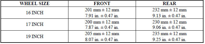
4. Compare the measurements to specifications listed in the following CURB HEIGHT SPECIFICATIONS chart. Maximum left-to-right differential is not to exceed 12.5 mm (0.5 in.).
5. If curb height is found to be out of specification and there is no sign of excessive body damage, curb height can be changed by replacing the applicable spring with a spring offering a different check load.
CURB HEIGHT SPECIFICATIONS
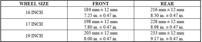
CURB HEIGHT SPECIFICATIONS - EXPORT

 Wheel alignment
PRE-WHEEL ALIGNMENT INSPECTION
Before any attempt is made to change or correct the wheel alignment, the
following inspection and necessary
corrections must be made to the vehicle to ensure proper ...
See also:
MEDIA CENTER 130 (RES/RSC) — AM/FM STEREO RADIO WITH CD PLAYER (MP3 AUX
JACK) AND SIRIUS RADIO
NOTE: The radio sales code is located on the lower right
side of the radio faceplate.
RES/RSC Radio
Operating Instructions — Radio Mode
NOTE: The ignition switch must be in the ON or ACC
posi ...
MAINTENANCE PROCEDURES
The pages that follow contain the required maintenance
services determined by the engineers who designed your
vehicle.
Besides those maintenance items specified in the fixed
maintenance schedule, ...
Installation
Fig. 51: Front Hub And Bearing Mounting
1. If required, install the hub and bearing (1) by sliding it into the
knuckle.
2. If installing hub and bearing, install the four bolts (2) fastening t ...
