
Dodge Journey: Core, service port valve
DESCRIPTION
Refrigerant system service ports are used to recover, recycle, evacuate, charge and test the A/C refrigerant system. Unique sizes are used on the two service ports for the R-134a refrigerant system to ensure the system is not accidentally contaminated with R-12 refrigerant or by service equipment used for R-12 refrigerant.
The high side service port is located on the A/C liquid line near the right front strut tower. The low side service port is located on the A/C suction line near the dash panel.
Both the high side and low side A/C service port valve cores are serviceable.
NOTE: The protective cap aids in service port sealing and helps protect the refrigerant system from contamination. Remember to always reinstall the protective caps onto the service ports when refrigerant system service is complete.
Each of the service ports has a threaded plastic protective cap installed over it from the factory. The service port caps are serviceable items.
REMOVAL
WARNING: Refer to the applicable warnings and cautions for this system before performing the following operation. Failure to follow the warnings and cautions may result in possible serious or fatal injury.
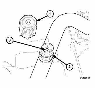
Fig. 229: Identifying A/C Service Port Components
NOTE: Typical A/C service port shown.
1. Remove the protective cap (1) from the service port (2).
2. Recover the refrigerant from the refrigerant system. 3. Using a Schrader-type valve core tool, remove the valve core (3) from the service port.
4. Install a plug in, or tape over the opened service port(s).
INSTALLATION
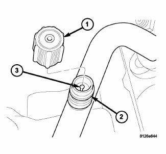
Fig. 230: Identifying A/C Service Port Components
NOTE: Typical A/C service port shown.
1. Lubricate the valve core (3) with clean refrigerant oil prior to installation. Use only refrigerant oil of the type recommended for the A/C compressor in the vehicle.
2. Remove the tape or plug from the service port (2).
CAUTION: A valve core that is not fully seated in the A/C service port can result in damage to the valve during refrigerant system evacuation and charge. Such damage may result in a loss of system refrigerant while uncoupling the charge adapters.
3. Using a Schrader-type valve core tool, install and tighten the valve core into the service port(s).
CAUTION: Do NOT run the engine with a vacuum pump in operation or with a vacuum present within the A/C system when equipped with the Denso 6SEU16 variable displacement compressor. Failure to follow this caution will result in serious A/C compressor damage.
4. Evacuate and charge the refrigerant system.
NOTE: The protective cap helps aid in service port sealing and helps protect the refrigerant system from contamination. Remember to always reinstall the protective cap onto the service port when refrigerant system service is complete.
5. Install the protective cap (1) onto the service port.
 Removal, Installation
Removal
WARNING: Refer to the applicable warnings and cautions for this
system before
performing the following operation. Failure to follow the warnings and
cautions may result in po ...

See also:
Description, Operation
DESCRIPTION
Fig. 4: Rear View Camera
The Rear View Camera (RVC) (4) (also known as ParkView), is a camera on chip
device utilizing
Complementary Metal Oxide Semiconductor (CMOS) technology. CMO ...
Removal
2.0L TURBO DIESEL
Fig. 2: Generator Cables
1. Remove engine cover.
2. Disconnect and isolate the negative battery cable.
3. Remove accessory drive belt.
4. Disconnect battery cable fro ...
Diagnosis and testing
EXCESSIVE EXHAUST SYSTEM NOISE
CONDITION
POSSIBLE
CAUSES
CORRECTION
EXCESSIVE EXHAUST NOISE
(UNDER HOOD)
1. Exhaust manifold cracked or
broken.2. Manifold to cyl ...
