Dodge Journey: Diagnosis and testing
EXCESSIVE EXHAUST SYSTEM NOISE
|
CONDITION |
POSSIBLE CAUSES | CORRECTION |
| EXCESSIVE EXHAUST NOISE (UNDER HOOD) | 1. Exhaust manifold cracked or
broken. 2. Manifold to cylinder head leak. 3. EGR Valve to manifold gasket leakage. 4. EGR Valve to EGR tube gasket leakage. 5. EGR tube to manifold tube leakage. 6. Exhaust flex-joint to manifold leak 7. Exhaust flex-joint. 8. Pipe and shell noise from front exhaust pipe. |
1. Replace manifold. 2. Tighten manifold and/or replace gasket. 3. Tighten fasteners or replace gasket. 4. Tighten fasteners or replace gasket. 5. Tighten tube nut. 6. Tighten joint fasteners and/or replace gasket. 7. Replace catalytic converter assembly. 8. Characteristic of single wall pipe. |
| EXCESSIVE EXHAUST NOISE | 1. Leak at exhaust pipe joints. 2. Burned or rusted out muffler assembly or exhaust pipe. 3. Burned or rusted out resonator. 4. Restriction in exhaust system. 5. Converter material in muffler. |
1. Tighten clamps at leaking
joints. 2. Replace muffler resonator tailpipe assembly or exhaust pipe with catalytic converter assembly. 3. Replace muffler resonator tailpipe assembly. 4. Perform Exhaust System Restriction Check. Replace component as necessary. 5. Replace muffler and converter assemblies. Check fuel injection and ignition systems for proper operation. |
RESTRICTION CHECK
Exhaust system restriction can be checked by measuring back pressure using the scan tool and PEP module pressure tester.
WARNING: The normal operating temperature of the exhaust system is very high.
Therefore, never work around or attempt to service any part of the exhaust system until it is cooled. Special care should be taken when working near the catalytic converter. The temperature of the converter rises to a high level after a short period of engine operation time.
1. Disconnect and remove the upstream (before catalytic converter) oxygen sensor. 2. Install the Exhaust Back Pressure Fitting Adaptor CH8519.
3. Connect the Low Pressure Sensor (15 psi) CH7063 to the back pressure fitting.
4. Following the PEP module instruction service information , connect all required cables to the scan tool and PEP module. Select the available menu options on the scan display screen for using the digital pressure gauge function.
5. Apply the park brake and start the engine.
6. With transmission in Park or Neutral, raise engine speed to 2000 RPM. Monitor the pressure readings on the scan. Back pressure should not exceed specified limit.
NOTE: For applications with dual catalytic converters, repeat test on opposite converter using the previous steps.
7. If pressure exceeds maximum limits, inspect exhaust system for restricted component. For further catalytic converter inspection procedures. Replace component(s) as necessary.
EXHAUST BACK PRESSURE LIMITS
| Exhaust Back Pressure Limit (Max) | |
| Vehicle in Park/Neutral (no load) @2000 RPM | 3.45 kPa (0.5 psi) |
LEAK TESTING
WARNING: The normal operating temperature of the exhaust system is very high.
Therefore, never work around or attempt to service any part of the exhaust system until it is cooled. Special care should be taken when working near the catalytic converter. The temperature of the converter rises to a high level after a short period of engine operation time.
1. Raise and support vehicle.
CAUTION: The air pressure must not exceed 4 psi, otherwise engine damage can occur.
2. Connect Tool 8404-EC or 8404-ECT, Exhaust Cone to an adjustable air pressure regulator.
3. Attach shop air to the air pressure regulator.
4. Adjust the air pressure regulator to 4 psi 5. Insert Tool 8404-EC or 8404-ECT, Exhaust Cone into the vehicle tail pipe.
6. If the vehicle is equipped with dual exhaust, use Tool 8404-EC or 8404-ECT, Exhaust Cone with equipped attached plug. Plug one side of the dual exhaust pipe. Pressurize the other as described.
7. Apply a mixture of liquid dish soap and water to the following areas:
- - All welded joints from 6 inches rearward of the downstream O2 sensor forward
- - O2 sensor seal points
- - O2 sensor boss welds
- - Flange/joint connection(s)
- - Exhaust manifold to cylinder head connection(s)
- - EGR solenoid gasket base and tube seal points (if equipped)
8. Watch for the liquid/soapy water to bubble.
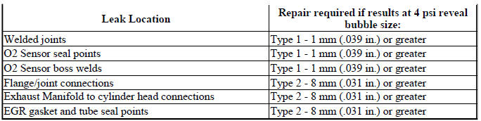
9. Use the following definitions to help determine if system or component repair/replacement is necessary:
- Type 1 Leak is defined as a leak where very small foam like bubbles 1mm (.039 in.) or less appear. Any Type 1 or greater leaks found in welded joints, O2 sensor seal points or O2 sensor boss welds must be repaired or the component must be replaced.
- Type 2 Leak is defined as a leak where larger bubbles 8mm (.031 in.) or greater appear. Any Type 2 or greater leaks found in flange or joint connections, exhaust manifold to cylinder head connections, or EGR gasket and tube seal points must be repaired or the components must be replaced.
If a leak is found that matches the above definition, repair or replace the component as necessary.
Once the repair is complete, repeat the procedure to verify that all leaks have been repaired.
 Description
Fig. 1: Muffler/Exhaust Pipe Assembly - Single Tail Pipe
- INSULATOR
- MUFFLER/EXHAUST PIPE ASSEMBLY
- BAND CLAMP
The exhaust system on the 2.4L and 2.7L engine models consists of a front ...
 Inspection, adjustments
INSPECTION
Inspect the exhaust pipes, catalytic converters, muffler, and resonators for
cracked joints, broken welds and
corrosion damage that would result in a leaking exhaust system. Inspect the ...
See also:
Fluid
STANDARD PROCEDURE
FLUID LEVEL AND CONDITION CHECK
FLUID LEVEL CHECK
Fig. 351: Identifying Fluid Level Indicator
- FLUID LEVEL INDICATOR
NOTE: Only transmission fluid of the type labele ...
Connector, data link
DESCRIPTION
Fig. 1: Data Link Connector
The Data Link Connector (DLC) (2) is a 16-way molded plastic connector
insulator on a dedicated take out of
the instrument panel wire harness. This conne ...
Inspection, adjustments
INSPECTION
Inspect the exhaust pipes, catalytic converters, muffler, and resonators for
cracked joints, broken welds and
corrosion damage that would result in a leaking exhaust system. Inspect the ...
