Dodge Journey: Sensor, coolant temperature
Description
There are two Engine Coolant Temperature (ECT) Sensors. One of the sensors threads into the block. The other sensor is located at the top of the coolant adapter housing. The ECT Sensor is a negative thermal coefficient sensor.
2.7L ENGINE
The Engine Coolant Temperature (ECT) Sensor threads into the coolant outlet connector. The ECT Sensor is a negative thermal coefficient sensor.
3.5L ENGINE
The Engine Coolant Temperature (ECT) Sensor threads into the lower intake manifold. The ECT Sensor is a negative thermal coefficient sensor.
Operation
The ECT sensor provides an input to the PCM. As temperature increases, resistance of the sensor decreases. As coolant temperature varies, the ECT sensor resistance changes resulting in a different voltage value at the PCM ECT sensor signal circuit. The ECT sensor provides input for various PCM operations. The PCM uses the input to control air-fuel mixture, timing, and radiator fan on/off times. The PCM uses ECT sensor input to send messages over the CAN bus to various modules for other functions such as temperature gauge and AC operation.
Removal
2.4L
CYLINDER BLOCK MOUNTED
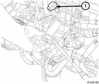
Fig. 104: ECT Sensor
- - ECT
1. Disconnect negative battery cable.
2. Partially drain cooling system below level of ECT Sensor.
3. Disconnect ECT Sensor electrical connector.
4. Remove ECT Sensor.
COOLANT ADAPTER MOUNTED
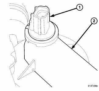
Fig. 105: ECT SENSOR AND COOLANT ADAPTER
- - ETC
- - COOLANT ADAPTER
1. Disconnect negative battery cable.
2. Partially drain cooling system below level of ECT Sensor (1).
3. Disconnect ECT Sensor electrical connector.
4. Remove ECT Sensor (1).
2.7L ENGINE
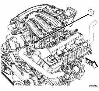
Fig. 106: ECT SENSOR 2.7L
- - ECT SENSOR
1. Partially drain cooling system below level of ECT sensor.
2. Remove upper intake manifold.
3. Disconnect ECT sensor electrical connector.
4. Remove ECT sensor.
3.5L ENGINE

Fig. 107: 3.5L THERMOSTAT HOUSING
- - THERMOSTAT HOUSING
- - RADIATOR HOSE
1. Disconnect negative battery cable.
2. Partially drain cooling system.
3. Disconnect coolant sensor electrical connector.
4. Remove coolant temperature sensor.
DIESEL ENGINE
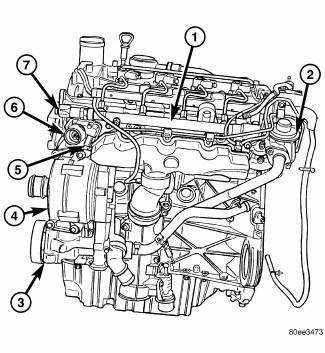
Fig. 108: THERMOSTAT AND SENSOR
- - FUEL RAIL
- - EGR VALVE
- - POWER STEERING PUMP
- - GENERATOR
- - COOLANT TEMPERATURE SENSOR
- - THERMOSTAT HOUSING
- - FUEL RAIL PRESSURE SENSOR
1. Disconnect negative battery cable.
2. Remove engine cover.
3. Partially drain coolant system below pressurized coolant recovery container.
4. Unplug coolant temperature sensor electrical connector.
NOTE: Capture any residual coolant that may flow.
5. Remove coolant temperature sensor (5).
Installation
2.4L
COOLANT ADAPTER MOUNTED

Fig. 109: ECT SENSOR AND COOLANT ADAPTER
- - ETC
- - COOLANT ADAPTER
1. Install ECT Sensor (1). Make sure coolant sensor is locked in place
2. Reconnect ECT Sensor electrical connector.
3. Fill cooling system.
4. Connect negative battery cable.
CYLINDER BLOCK MOUNTED

Fig. 110: ECT Sensor
- - ECT
1. Install ECT Sensor. Tighten sensor to 19 N.m (168 in. lbs.).
2. Reconnect ECT Sensor electrical connector.
3. Fill cooling system.
4. Connect negative battery cable.
2.7L ENGINE

Fig. 111: ECT SENSOR 2.7L
- - ECT SENSOR
1. Install ECT sensor. Tighten sensor to 19 N.m (168 in. lbs.).
2. Reconnect ECT sensor electrical sensor.
3. Fill cooling system.
3.5L ENGINE
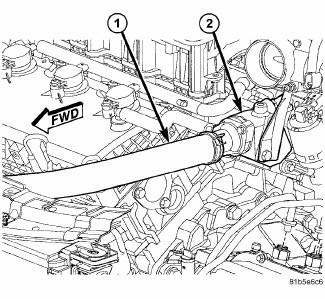
Fig. 112: 3.5L THERMOSTAT HOUSING
- - THERMOSTAT HOUSING
- - RADIATOR HOSE
1. Install engine coolant temperature sensor. Tighten sensor to 28 N.m (20 ft. lbs.) torque.
2. Attach electrical connector to sensor.
3. Fill cooling system.
4. Connect negative battery cable.
DIESEL ENGINE

Fig. 113: THERMOSTAT AND SENSOR
- - FUEL RAIL
- - EGR VALVE
- - POWER STEERING PUMP
- - GENERATOR
- - COOLANT TEMPERATURE SENSOR
- - THERMOSTAT HOUSING
- - FUEL RAIL PRESSURE SENSOR
1. Position and install coolant temperature sensor (5).
2. Connect coolant temperature sensor electrical connector.
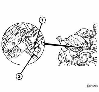
Fig. 114: ENGINE COOLANT TEMPERATURE SENSOR
- - RETAINING CLAMP
- - ENGINE COOLANT TEMPERATURE SENSOR
3. Refill coolant system to proper level with proper mixture of coolant.
4. Install engine cover.
5. Connect negative battery cable.
WARNING: Use extreme caution when engine is operating. Do not stand in a direct line with fan. Do not put your hands near pulleys, belts or fan.
Do not wear loose clothes.
6. Start engine and inspect for leaks.
 Radiator, engine cooling
Description
Fig. 99: COOLING SYSTEM - OVERVIEW
- WINDSHIELD WASHER RESERVOIR
- UPPER SUPPORT
- FAN SHROUD
- FAN MOTOR
- LOWER RADIATOR HOSE
All vehicles are equipped with a cross flo ...
 Thermostat
Description
2.0L DIESEL/2.4L ENGINE
Fig. 115: THERMOSTAT
- AIR BLEED
- SEAL
- RETURN SPRING
- PELLET CHAMBER
The primary thermostat for the 2.0L diesel and 2.4L gas engines are locate ...
See also:
Description, Operation
DESCRIPTION
Fig. 7: Blend Door Actuators
The blend door actuators (1) for the front heating-A/C system are reversible,
12-volt direct current (DC) servo
motors. Models with the front single zon ...
Disassembly
NOTE: The strut assembly must be removed from the vehicle for it to be
disassembled
and assembled.
For the disassembly and assembly of the strut assembly, use strut spring
compressor, tea ...
Diagnosis and Testing
STRUT ASSEMBLY
Fig. 80: Strut Assembly (Exploded)
Inspect the strut assembly for the following conditions:
Inspect for a damaged or broken coil spring (7).
Inspect for a torn or damaged dust ...
