Dodge Journey: Ring(s), piston
Standard Procedure
PISTON RING FITTING
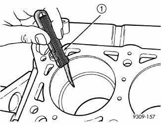
Fig. 200: CHECK GAP ON PISTON RINGS
- - FEELER GAUGE
1. Wipe cylinder bore clean. Insert ring and push down with piston to ensure it is square in bore. The ring gap measurement must be made with the ring positioning at least 12 mm (0.50 inch.) from bottom of cylinder bore. Check gap with feeler gauge (1). Refer to Engine - Specifications for clearance measurements.
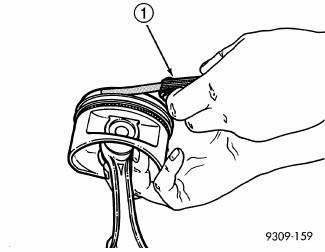
Fig. 201: Measuring Piston Ring Side Clearance
- - FEELER GAUGE
2. Check piston ring to groove clearance (1).
Removal
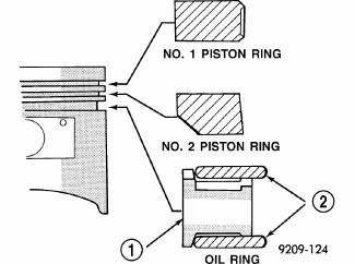
Fig. 202: PISTON RING - INSTALLATION
- - SPACER EXPANDER
- - SIDE RAIL
1. Remove piston and connecting rod.
2. Remove No. 1 and No. 2 piston rings from piston using a ring expander tool.
3. Remove upper oil ring side rail.
4. Remove lower oil ring side rail.
5. Remove oil ring expander.
Installation
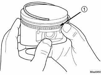
Fig. 203: SIDE RAIL - INSTALLATION
- - SIDE RAIL END
1. Measure clearance of piston rings to the cylinder bore and piston.
CAUTION: Install piston rings in the following order:
- Oil ring expander.
- Upper oil ring side rail.
- Lower oil ring side rail.
- No. 2 Intermediate piston ring.
- No. 1 Upper piston ring.
2. Install oil ring expander.
Install the side rail (1) by placing one end between the piston ring groove and the oil ring expander. Hold end firmly and press down the portion to be installed until side rail is in position. Do not use a piston ring expander during this step.
3. Install upper side rail first and then the lower side rail.
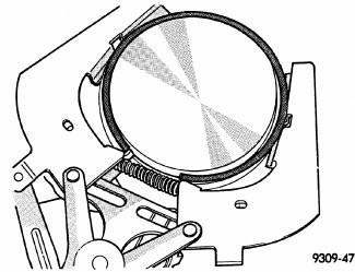
Fig. 204: Upper and Intermediate Rings - Installation
NOTE: The No. 1 and No. 2 piston rings have a different cross section. Ensure No.
2 ring is installed with manufacturers I.D. mark (dot) facing up, towards top of the piston.
4. Install No. 2 piston ring and then No. 1 piston ring.
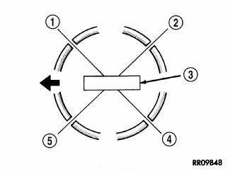
Fig. 205: PISTON RING END GAP POSITION
- - SIDE RAIL UPPER
- - NO. 1 RING GAP
- - PISTON PIN
- - SIDE RAIL LOWER
- - NO. 2 RING GAP AND SPACER EXPANDER GAP
 Flexplate
Removal
Fig. 198: Flex Plate
1. Remove transmission.
2. Remove flex plate attaching bolts (2).
3. Remove backing plate (3) and flex plate (1).
Installation
Fig. 199: FLEX PLATE
1. Posit ...
 Rod, piston and connecting
Description
Fig. 206: Piston & Connecting Rod
- "F" TOWARD FRONT OF ENGINE
- RING COMPRESSOR
- SPECIAL TOOL 8189
- OIL SQUIRT HOLE
The pistons (1) are made of a high stre ...
See also:
Module, heated seat
DESCRIPTION
Fig. 35: Locating Heated Seat Module
The heated seat module (2) is located under the driver front seat. It has a
single electrical connector (1) and a
push pin style retainer that s ...
POWER SUNROOF — IF EQUIPPED
The power sunroof switch is located between the sun
visors on the overhead console.
Power sunroof Switch
WARNING:
• Never leave children in a vehicle with the key in
the ignition switch. Occu ...
SAFETY TIPS
Transporting Passengers
NEVER TRANSPORT PASSENGERS IN THE CARGO
AREA.
WARNING:
• Do not leave children or animals inside parked
vehicles in hot weather. Interior heat build-up may
cause seriou ...
