Dodge Journey: Diagnosis and testing
ON-BOARD DIAGNOSTIC SYSTEM
The Powertrain Control Module (PCM) monitors critical input and output circuits of the charging system, making sure they are operational. A Diagnostic Trouble Code (DTC) is assigned to each input and output circuit monitored by the OBD system. Some circuits are checked continuously and some are checked only under certain conditions.
If the OBD system senses that a monitored circuit is bad, it will put a DTC into electronic memory. The DTC will stay in electronic memory as long as the circuit continues to be bad. The PCM is programmed to clear the memory after 40 good trips if the problem does not occur again.
DIAGNOSTIC TROUBLE CODES
A DTC description can be read using the scan tool. Refer to the appropriate Powertrain Diagnostic article for information.
A DTC does not identify which component in a circuit is bad. Thus, a DTC should be treated as a symptom, not as the cause for the problem. In some cases, because of the design of the diagnostic test procedure, a DTC can be the reason for another DTC to be set. Therefore, it is important that the test procedures be followed in sequence, to understand what caused a DTC to be set.
ERASING DIAGNOSTIC TROUBLE CODES
The scan tool must be used to erase a DTC.
The following procedures may be used to diagnose the charging system if:
- the check gauges lamp or battery lamp is illuminated with the engine running
- the voltmeter (if equipped) does not register properly
- an undercharged or overcharged battery condition occurs.
Remember that an undercharged battery is often caused by:
- accessories being left on with the engine not running
- a faulty or improperly adjusted switch that allows a lamp to stay on. Refer to Ignition-Off Draw Test.
- loose generator belt.
INSPECTION
The Powertrain Control Module (PCM) monitors critical input and output circuits of the charging system, making sure they are operational. A Diagnostic Trouble Code (DTC) is assigned to each input and output circuit monitored by the On-Board Diagnostic (OBD) system. Some charging system circuits are checked continuously, and some are checked only under certain conditions.
Refer to Diagnostic Trouble Codes in; Powertrain Diagnostic service information for more DTC information.
This will include a complete list of DTC's including DTC's for the charging system.
To perform a complete test of the charging system, refer to the appropriate Powertrain Diagnostic Procedures service information and the scan tool. Perform the following inspections before attaching the scan tool.
1. Inspect the battery condition.
2. Inspect condition of battery cable terminals, battery posts, connections at engine block, starter solenoid and relay. They should be clean and tight. Repair as required.
3. Inspect all fuses in the fuseblock for tightness in receptacles. They should be properly installed and tight.
Repair or replace as required.
4. Inspect generator mounting bolts for tightness. Replace or tighten bolts if required. Refer to Specifications. Also refer to GENERATOR Removal/Installation procedures.
5. Inspect generator drive belt condition and tension. Tighten or replace belt as required.
6. Inspect decoupler pulley (if equipped). Ensure decoupler pulley is driving the alternator rotor.
7. Inspect automatic belt tensioner (if equipped).
8. Inspect generator electrical connections at generator field, battery output, and ground terminal (if equipped). Also check generator ground wire connection at engine (if equipped). They should all be clean and tight. Repair as required.
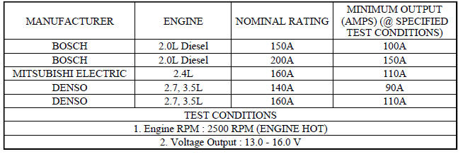
SPECIFICATIONS
GENERATOR
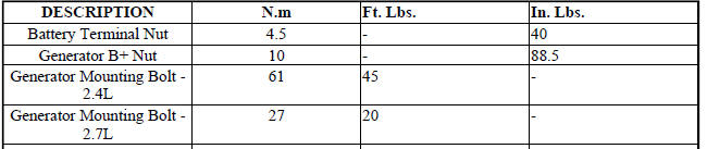
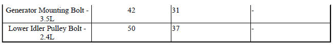
TORQUE
 Description, Operation
DESCRIPTION
The charging system consists of:
Generator
Decoupler Pulley (2.4L and Diesel Only)
Electronic Voltage Regulator (EVR) circuitry within the Powertrain
Control Module (PCM)
Ign ...
 Generator
...
See also:
Disassembly
Fig. 200: Snap Ring At Output Shaft Case Bearing
1. Remove the snap ring (2) from the output shaft.
Fig. 201: Output Shaft Case Bearing And Gear
2. Use Bearing Splitter P-334 (3), Cage 8925-3 ( ...
Description, Operation
DESCRIPTION
WARNING: Due to propeller shaft imbalance concerns, the propeller
shaft can only be
serviced as an assembly.
AWD models utilize a "three-piece" propeller sha ...
Standard procedure, Cleaning, Inspection
Standard procedure
BATTERY RECONNECTION
NOTE: This reconnection procedure is to be performed anytime the
battery has been
disconnected.
1. Connect the negative battery cable remote termin ...
