Dodge Journey: Module, satellite video
REMOVAL
1. Disconnect and isolate the negative battery cable.
2. Move the front passenger seat to the most forward position.

Fig. 8: Antenna & Electrical Connectors
3. Disconnect the three antenna connectors (1) and the electrical connector (2).
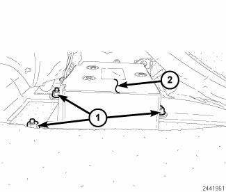
Fig. 9: Retainers & Video Module Housing
4. Remove the three retainers (1) securing the video module housing (2) to the floor, remove video housing and module from vehicle.

Fig. 10: Video Module Retainers & Video Module Housing
5. Remove the video module retainers (1) to the video module housing (2).
INSTALLATION
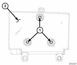
Fig. 11: Video Module Retainers & Video Module Housing
1. Install the video module to the housing.

Fig. 12: Retainers & Video Module Housing
2. Install the video module into the vehicle and Install the three retainers (1) securing the video module housing (2) to the floor.
Tighten to 6 N.m (53 in. lbs.).
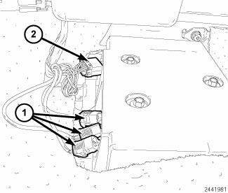
Fig. 13: Antenna & Electrical Connectors
3. Connect the three antenna connectors (1) and the electrical connector (2).
4. Move the front passenger seat back to the original position.
5. Connect the battery negative cable.
 Removal, Installation
REMOVAL
Fig. 6: Backup Camera & Liftgate & Lights
1. Disconnect the negative battery cable.
2. Remove the four retainers (1) holding the lightbar (5) to the liftgate (6).
3. Using a ...
 Monitor, media system
REMOVAL
Fig. 14: Removing / Installing Mounting Fasteners
1. Disconnect and isolate the battery negative cable.
2. Open the video screen to access the mounting fasteners.
3. Remove the mount ...
See also:
Installation
CLUTCH - FIXED DISPLACEMENT A/C COMPRESSOR
NOTE: Typical A/C compressor and clutch assembly shown in
illustrations.
Fig. 214: Clutch Coil & Snap Ring
1. Align the dowel pin on the bac ...
Standard Procedure
REFRIGERANT OIL LEVEL
When an A/C system is assembled at the factory, all components except the A/C
compressor are refrigerant oil
free. After the refrigerant system has been charged and operated, ...
Differential, transaxle
DESCRIPTION
Fig. 166: Differential Assembly
- RING GEAR
- PINION SHAFT
- DIFFERENTIAL CASE
- PINION GEAR
- SIDE GEAR
The BG6 differential is a conventional open design, and is integr ...
