Dodge Journey: Monitor, media system
REMOVAL

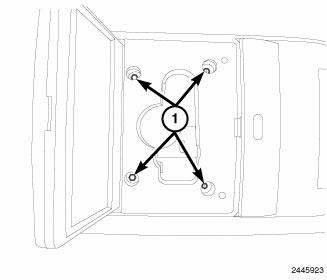
Fig. 14: Removing / Installing Mounting Fasteners
1. Disconnect and isolate the battery negative cable.
2. Open the video screen to access the mounting fasteners.
3. Remove the mounting fasteners.

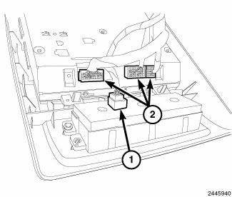
Fig. 15: Removing/Installing Video Monitor Connectors
4. If equipped, disconnect the rear heat control connector (1).
5. Disconnect the video monitor connectors (2) and remove the assembly from the vehicle.

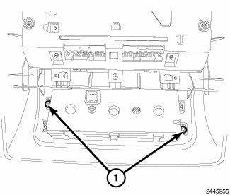
Fig. 16: Fasteners
6. Remove the fasteners (1) and remove the rear A/C and heater control.
INSTALLATION

Fig. 17: Fasteners
1. Install the rear A/C and heater control and the fasteners (1).

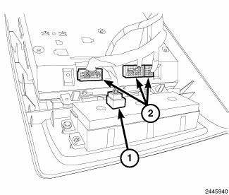
Fig. 18: Removing/Installing Video Monitor Connectors
2. If equipped, connect the rear A/C and heater control connector (1).
3. Connect the video monitor connectors (2).

Fig. 19: Removing / Installing Mounting Fasteners
4. Install the mounting fasteners.
5. Connect the battery negative cable.
 Module, satellite video
REMOVAL
1. Disconnect and isolate the negative battery cable.
2. Move the front passenger seat to the most forward position.
Fig. 8: Antenna & Electrical Connectors
3. Disconnect the three ...
 Radio
Radio
STANDARD PROCEDURE
RADIO BACKUP
The radio hard disk drive (HDD) can be backed up to save customer data in the
event that a radio replacement is
required. This procedure can only be done with all ...
See also:
ELECTRONIC SPEED CONTROL — IF EQUIPPED
When engaged, the Electronic Speed Control takes over
the accelerator operation at speeds greater than 25 mph
(40 km/h).
The Electronic Speed Control lever is located on the right
side of the stee ...
Description, Operation
DESCRIPTION
The battery cables are large gauge, stranded copper wires sheathed within a
heavy plastic or synthetic rubber
insulating jacket. The wire used in the battery cables combines excellent ...
Description
The parking brake consists of the following components:
Foot-operated parking brake lever *
Cables (front, left rear, right rear)
Cable equalizer
Caliper with Integral Parking Brake (IPB)
...
