Dodge Journey: Sensor, speed, input
DESCRIPTION

Fig. 369: Removing/Installing Input Speed Sensor
- - INPUT SPEED SENSOR
The Input Speed Sensor (1) , is a two-wire magnetic pickup device that generates AC signals as rotation occurs.
It is threaded into the transaxle case.

Fig. 370: Identifying Input Speed Sensor & O-Ring
- - INPUT SPEED SENSOR
- - O-RING
The Input Speed Sensor (1) is sealed with an O-ring (2) , and is considered a primary input to the Powertrain/Transmission Control Module.
OPERATION
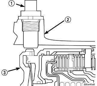
Fig. 371: Identifying Input Speed Sensor & Input Clutch Hub
- - INPUT SPEED SENSOR
- - TRANSAXLE CASE
- - INPUT CLUTCH HUB
The Input Speed Sensor (1) provides information on how fast the input shaft is rotating. As the teeth of the input clutch hub (3) pass by the sensor coil, an AC voltage is generated and sent to the PCM/TCM. The PCM/TCM interprets this information as input shaft RPM.
The PCM/TCM compares the input speed signal with output speed signal to determine the following:
- Transmission gear ratio
- Speed ratio error detection
- CVI calculation
The PCM/TCM also compares the input speed signal and the engine speed signal to determine the following:
- Torque converter clutch slippage
- Torque converter element speed ratio
REMOVAL
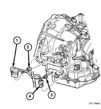
Fig. 372: Identifying Transmission Connectors
- - SOLENOID PACK CONNECTOR
- - INPUT SPEED SENSOR CONNECTOR
- - OUTPUT SPEED SENSOR CONNECTOR
- - TRANSMISSION RANGE SENSOR CONNECTOR
1. Disconnect battery negative cable.
2. Disconnect input speed sensor connector (2) .
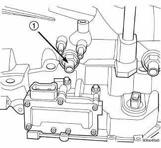
Fig. 373: Removing/Installing Input Speed Sensor
- - INPUT SPEED SENSOR
3. Unscrew and remove input speed sensor (1) .
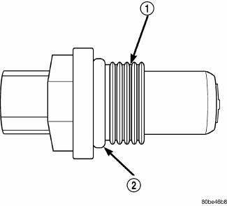
Fig. 374: Identifying Input Speed Sensor & O-Ring
- - INPUT SPEED SENSOR
- - O-RING
4. Inspect speed sensor O-ring (2) and replace if necessary.
INSTALLATION

Fig. 375: Identifying Input Speed Sensor & O-Ring
- - INPUT SPEED SENSOR
- - O-RING
1. Verify O-ring (2) is installed into position.

Fig. 376: Removing/Installing Input Speed Sensor
- - INPUT SPEED SENSOR
2. Install and tighten input speed sensor (1) to 27 N.m (20 ft. lbs.).

Fig. 377: Identifying Transmission Connectors
- - SOLENOID PACK CONNECTOR
- - INPUT SPEED SENSOR CONNECTOR
- - OUTPUT SPEED SENSOR CONNECTOR
- - TRANSMISSION RANGE SENSOR CONNECTOR
3. Connect speed sensor connector (4) .
4. Connect battery negative cable.
 Seal, oil pump
REMOVAL
Fig. 367: Removing Oil Pump Seal
- SEAL PULLER C-3981-B
- OIL PUMP SEAL
1. Remove transaxle from vehicle.
2. Using Seal Puller C-3981B (1) , remove oil pump seal (2).
INSTALLA ...
 Sensor, speed, output
DESCRIPTION
Fig. 378: Identifying Output Speed Sensor
- OUTPUT SPEED SENSOR
The Output Speed Sensor (1) is a two-wire magnetic pickup device that
generates an AC signal as rotation
occurs ...
See also:
Wiring, trailer tow
DESCRIPTION
Fig. 73: Instruction Sheet Are Placed In Glove Box
Vehicles equipped with an optional Trailer Tow Preparation package have a
trailer tow wiring harness and an
instruction sheet (1) ...
WINDOWS
Power Windows
The window controls on the driver’s door trim panel
control all of the door windows.
Power Window Switches
There are single window controls on each passenger door
trim panel, wh ...
FLUIDS, LUBRICANTS, AND GENUINE PARTS
Engine
Chassis ...
