Dodge Journey: Removal, Installation
REMOVAL
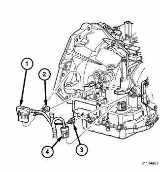
Fig. 298: Identifying Transmission Connectors
- - SOLENOID PACK CONNECTOR
- - INPUT SPEED SENSOR CONNECTOR
- - OUTPUT SPEED SENSOR CONNECTOR
- - TRANSMISSION RANGE SENSOR CONNECTOR
NOTE: If solenoid/pressure switch assembly is being replaced, the "Quick-Learn" procedure must be performed.
1. Disconnect battery negative cable.
2. Remove air cleaner assembly.
3. Disconnect solenoid/pressure switch assembly connector (1) .
4. Disconnect input speed sensor connector (2).
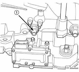
Fig. 299: Removing/Installing Input Speed Sensor
- - INPUT SPEED SENSOR
5. Remove input speed sensor (1) .
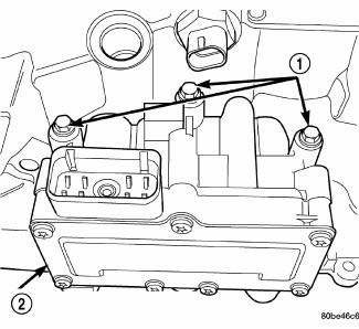
Fig. 300: Removing/Installing Solenoid/Pressure Switch Assembly-To-Transaxle
Case Bolts
- - BOLTS
- - SOLENOID AND PRESSURE SWITCH ASSEMBLY
6. Remove three solenoid/pressure switch assembly-to-transaxle case bolts (1) .
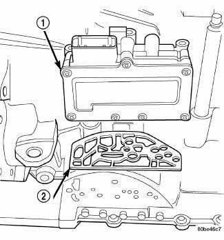
Fig. 301: Removing/Installing Solenoid/Pressure Switch Assembly & Gasket
- - SOLENOID/PRESSURE SWITCH ASSEMBLY
- - GASKET
7. Remove solenoid/pressure switch assembly (1) and gasket (2). Use care to prevent gasket material and foreign objects from become lodged in the transaxle case ports.
INSTALLATION
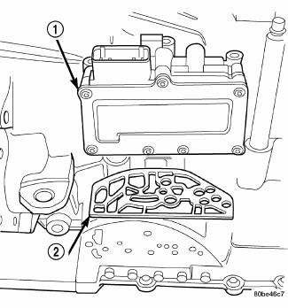
Fig. 302: Removing/Installing Solenoid/Pressure Switch Assembly & Gasket
- - SOLENOID/PRESSURE SWITCH ASSEMBLY
- - GASKET
NOTE: If solenoid/pressure switch assembly is being replaced, it is necessary to perform the "Quick-Learn" procedure.
1. Install solenoid/pressure switch assembly and new gasket to transaxle .
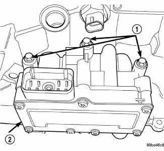
Fig. 303: Removing/Installing Solenoid/Pressure Switch Assembly-To-Transaxle
Case Bolts
- - BOLTS
- - SOLENOID AND PRESSURE SWITCH ASSEMBLY
2. Install and torque three bolts (1) to 12 N.m (105 in. lbs.).
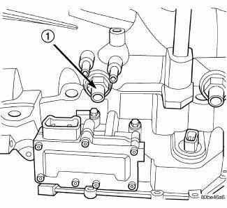
Fig. 304: Removing/Installing Input Speed Sensor
- - INPUT SPEED SENSOR
3. Install input speed sensor (1) and torque to 27 N.m (20 ft. lbs.).
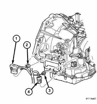
Fig. 305: Identifying Transmission Connectors
- - SOLENOID PACK CONNECTOR
- - INPUT SPEED SENSOR CONNECTOR
- - OUTPUT SPEED SENSOR CONNECTOR
- - TRANSMISSION RANGE SENSOR CONNECTOR
4. Connect input speed sensor connector (2) .
5. Install solenoid/pressure switch 8-way connector and torque to 4 N.m (35 in. lbs.).
6. Install air cleaner assembly.
7. Connect battery negative cable.
8. If solenoid/pressure switch assembly was replaced, perform the "Quick-Learn" procedure.
 Description, Operation
DESCRIPTION
Fig. 297: Identifying Solenoid/Pressure Switch Assembly
- SOLENOID AND PRESSURE SWITCH ASSEMBLY
The Solenoid/Pressure Switch Assembly (1) is external to the transaxle and
mount ...
 Cable, shift
REMOVAL
Fig. 306: Identifying Knee Blocker
1. Remove the knee blocker (2).
Fig. 307: Identifying Shift Cable At Shifter
NOTE: Ensure the lock tab on the shift cable (2) is depressed before ...
See also:
Installation
NOTE: Perform 1 through 6 on each side of vehicle to complete pad set
installation,
then proceed to 7.
CAUTION: Anytime the brake rotor or brake pads are being replaced,
the rear cal ...
Removal
FRONT
1. Raise and support the vehicle.
Fig. 163: TIRE AND WHEEL MOUNTING
2. Remove the wheel mounting nuts (3), then the tire and wheel assembly (1).
NOTE: In some cases, it may be necessary ...
Switch, backup lamp
DESCRIPTION
Fig. 43: Backup Lamp Switch
Vehicles equipped with a manual transmission (2) have a normally open,
spring-loaded plunger type backup
lamp switch (1). Vehicles with an optional elect ...
