Dodge Journey: Schematics and diagrams
40/41TE - WITH VARIABLE LINE PRESSURE
Fig. 181: Identifying Line Pressure - Park & Neutral
Fig. 182: Identifying Line Pressure - Reverse
Fig. 183: Identifying Line Pressure - First Gear (Drive)
Fig. 184: Identifying Line Pressure - Second Gear (Drive)
Fig. 185: Identifying Line Pressure - Second Gear EMCC (Drive)
Fig. 186: Identifying Line Pressure - Direct Gear (Drive)
Fig. 187: Identifying Line Pressure - Direct Gear EMCC (Drive)
Fig. 188: Identifying Line Pressure - Fourth Gear Overdrive (Drive)
Fig. 189: Identifying Line Pressure - Fourth Gear Overdrive EMCC (Drive)
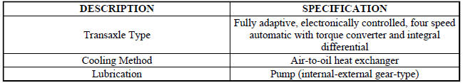
SPECIFICATIONS
GENERAL SPECIFICATIONS
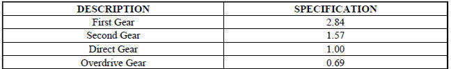
GEAR RATIOS

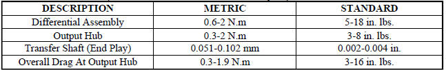
BEARING SETTINGS (END PLAY AND TURNING TORQUE)
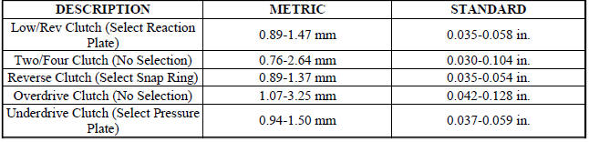
CLUTCH CLEARANCES
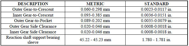
OIL PUMP CLEARANCES
INPUT SHAFT

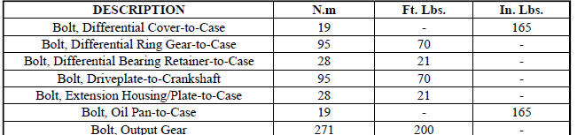
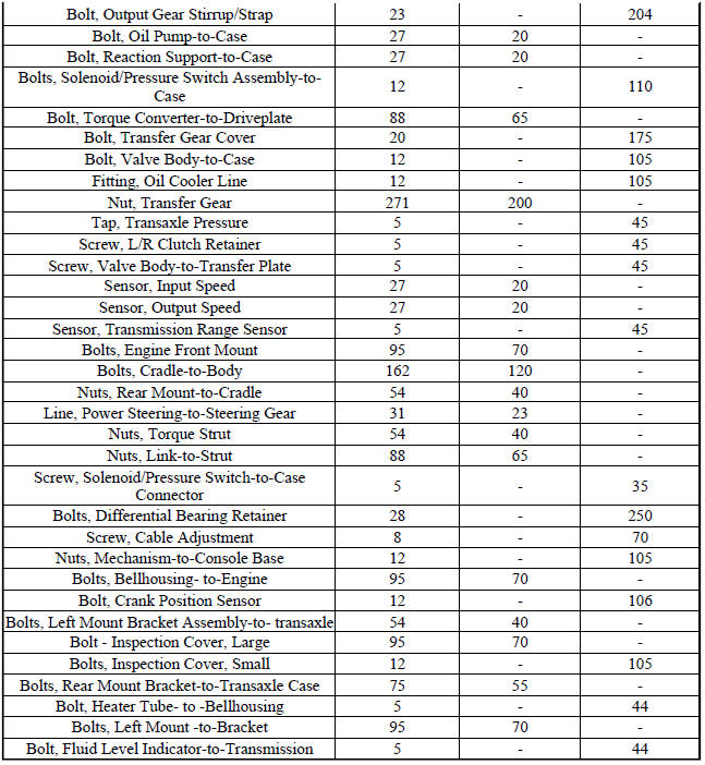
TORQUE SPECIFICATIONS
SPECIAL TOOLS
Fig. 190: Puller C-637
Fig. 191: Pressure Gauge (High) C-3293SP
Fig. 192: Dial Indicator C-3339
Fig. 193: Oil Pump Puller C-3752
Fig. 194: Seal Puller C-3981B
Fig. 195: Universal Handle C-4171
Fig. 196: Seal Installer C-4193A
Fig. 197: Adapter C-4996
Fig. 198: Remover Kit L-4406
Fig. 199: Gear Puller L-4407A
Fig. 200: Bearing Installer L-4410
Fig. 201: Gear Checking Plate L-4432
Fig. 202: Bearing Puller L-4435
Fig. 203: Differential Tool L-4436A
Fig. 204: Special Jaw Set L-4518
Fig. 205: Installer L-4520
Fig. 206: Thrust Button L-4539-2
Fig. 207: Adapter L-4559
Fig. 208: Adapter L-4559-2
Fig. 209: Bearing Splitter P-334
Fig. 210: Puller Set 5048
Fig. 211: Remover/Installer 5049-A
Fig. 212: Installer 5050A
Fig. 213: Installer 5052
Fig. 214: Compressor 5058A
Fig. 215: Compressor 5059-A
Fig. 216: Installer 5067
Fig. 217: Pliers 6051
Fig. 218: Installer 6052
Fig. 219: Installer 6053
Fig. 220: Button 6055
Fig. 221: Plate 6056
Fig. 222: Disk 6057
Fig. 223: Installer 6061
Fig. 224: Remover 6062-A
Fig. 225: Holder 6259
Fig. 226: Bolt 6260
Fig. 227: Installer 6261
Fig. 228: Tip 6268
Fig. 229: Remover/Installer 6301
Fig. 230: Remover/Installer 6302
Fig. 231: Installer 6536-A

Fig. 232: Puller 7794-A
Fig. 233: End Play Socket Set 8266
Fig. 234: Input Clutch Pressure Fixture 8391
Fig. 235: Driveline Support Table 8874
Fig. 236: Driveline Support Fixture 8534B
Fig. 237: Steering Shaft Roll Pin Remover/Installer 6831A
 Installation
Fig. 164: Removing/Installing Bellhousing Upper & Lower Bolts
NOTE: If transaxle assembly is being replaced or overhauled (clutch
and/or seal
replacement), it is necessary to perform th ...
 Accumulator
DESCRIPTION
Fig. 238: Identifying Underdrive & Overdrive Accumulators
- RETURN SPRING
- UNDERDRIVE CLUTCH ACCUMULATOR
- SEAL RING (2)
- OVERDRIVE CLUTCH ACCUMULATOR
The 41TE underd ...
See also:
Diagnosis and Testing
STRUT ASSEMBLY
Fig. 80: Strut Assembly (Exploded)
Inspect the strut assembly for the following conditions:
Inspect for a damaged or broken coil spring (7).
Inspect for a torn or damaged dust ...
STORAGE
Instrument Panel Storage Compartment — If
Equipped
Press and release the button on the door to open it. The
door swings upward to allow easy access to the compartment.
Instrument Panel Storage ...
TIRE CHAINS
Due to limited clearance, tire chains are not recommended.
CAUTION:
Damage to the vehicle may result if tire chains are
used. ...
