Dodge Journey: Hub and bearing
DESCRIPTION
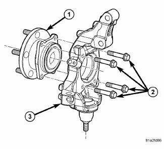
Fig. 31: Front Hub And Bearing Mounting
The front wheel bearing and wheel hub of this vehicle are a one piece sealed unit or hub and bearing unit type assembly.
The hub and bearing (1) is mounted to the knuckle using four mounting bolts (2) and to the axle half shaft using a retaining nut. The center of the hub and bearing is splined to match the outer joint of the axle half shaft.
Each front hub and bearing has five wheel mounting studs on the hub flange for mounting the wheel to the vehicle. The wheel mounting studs are the only replaceable components of the hub and bearing. Otherwise, the hub and bearing is serviced as a complete assembly.
Diagnosis and Testing
HUB AND BEARING
NOTE: The wheel bearing is designed to last for the life of the vehicle and requires no type of periodic maintenance.
The following procedure may be used for diagnosing the condition of the hub and bearing.
1. Remove the wheel and tire assembly, disc brake caliper and brake rotor.
2. Rotate the wheel hub checking for resistance or roughness.
Any roughness or resistance to rotation may indicate dirt intrusion or a failed hub bearing. If the bearing exhibits any of these conditions, the hub bearing will require replacement. Do not attempt to disassemble the bearing for repair. If the wheel bearing is disassembled for any reason, it must be replaced.
Damaged bearing seals and the resulting excessive grease loss may also require hub and bearing replacement.
Moderate grease weeping from the bearing is considered normal and should not require replacement of the hub and bearing.
To diagnose a bent hub, measure hub runout.
REMOVAL
NOTE: Before proceeding, review all Warnings and Cautions.
1. Raise and support the vehicle.
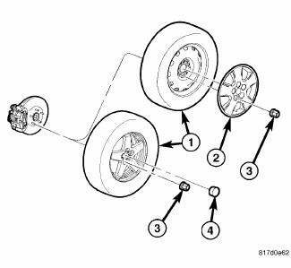
Fig. 32: TIRE AND WHEEL MOUNTING
2. Remove the wheel mounting nuts (3), then the tire and wheel assembly (1).
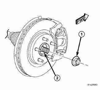
Fig. 33: View Of Hub Nut & Axle Shaft
3. While a helper applies the brakes to keep the hub from rotating, remove the hub nut (1) from the axle half shaft (2).
4. Access and remove the front brake rotor.
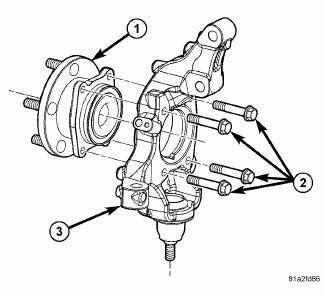
Fig. 34: Front Hub And Bearing Mounting
5. Remove the four bolts (2) fastening the hub and bearing to the knuckle (3).
6. Slide the hub and bearing (1) off the half shaft and out of the knuckle.
INSTALLATION
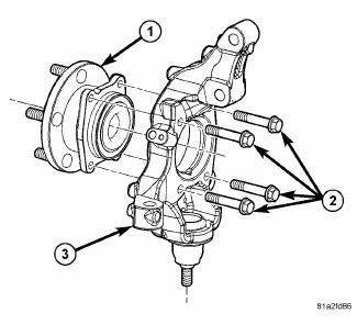
Fig. 35: Front Hub And Bearing Mounting
1. Install the hub and bearing (1) by sliding it over the half shaft and into the knuckle.
2. Install the four bolts (2) fastening the hub and bearing (1) to the knuckle (3). Tighten the four bolts to 82 N.m (60 ft. lbs.).
3. Install the brake rotor, disc brake caliper and adapter.
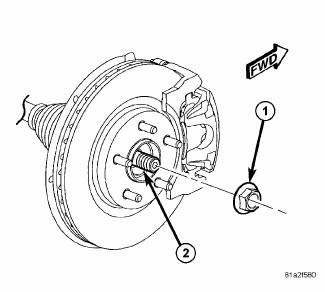
Fig. 36: View Of Hub Nut & Axle Shaft
NOTE: Always install a new hub nut. The original hub nut is one-time use only and should be discarded when removed.
4. Clean all foreign matter from the threads of the half shaft outer C/V joint.
5. Install the hub nut (1) on the end of the half shaft (2) and lightly tighten it.
6. While a helper applies the brakes to keep the hub from rotating, tighten the hub nut (1) to 132 N.m (97 ft.lbs.).
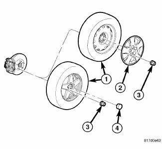
Fig. 37: TIRE AND WHEEL MOUNTING
7. Install the tire and wheel assembly (1). Install and tighten wheel mounting nuts (3) to 135 N.m (100 ft. lbs.).
8. Lower the vehicle.
 Installation
Fig. 25: Ball Joint Installation
1. Install Installer (2), Special Tool 9964-1, and Installer (4), Special
Tool 9964-2 on Remover/Installer (5),
Special Tool 8441-1. Place a new ball joint (stem ...
See also:
Installation
FRONT
NOTE: Inspect disc brake pads before installation.
Fig. 169: VENTED BRAKE ROTOR MOUNTING
1. Clean the hub face (1) to remove any dirt or corrosion where the rotor
mounts.
2. Insta ...
Switch, defogger, rear
DESCRIPTION
Fig. 5: EBL Switch (MTC)
NOTE: Manual tri-zone temperature A/C-heater control shown in
illustration. Other A/Cheater
controls similar.
The momentary push-button swi ...
Fuel system
FUEL SYSTEM
Fuel System Similar Conditions Window - An indicator that 'Absolute MAP
When Fuel Sys Fail' and
'RPM When Fuel Sys Failed' are all in the same range when the failure
occurred. ...

