Dodge Journey: Switch, defogger, rear
DESCRIPTION
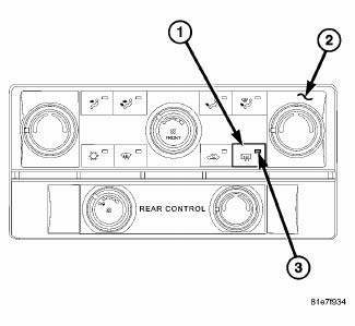
Fig. 5: EBL Switch (MTC)
NOTE: Manual tri-zone temperature A/C-heater control shown in illustration. Other A/Cheater controls similar.
The momentary push-button switch (1) for the rear window defogger (EBL) system is located in the A/C-heater control (2) in the center of the instrument panel. An amber indicator (3) will illuminate to indicate when the EBL system is turned on.
OPERATION
An amber indicator will illuminate when the rear window defogger switch is activated. When activated, the switch sends a request signal to the totally integrated power module (TIPM) to energize the internal EBL high side driver to provide battery current to the rear window defogger grid lines and to the heated side view mirrors, when equipped.
NOTE: The EBL system turns off automatically after 10 minutes of initial operation.
Each following activation cycle of the EBL system will last 5 minutes.
The rear window defogger switch is diagnosed using a scan tool. The rear window defogger switch and indicator cannot be adjusted or repaired. The A/C-heater control must be replaced if the rear window defogger switch or indicator is inoperative or damaged.
 Grid, defogger, rear
STANDARD PROCEDURE
GRID LINE AND TERMINAL REPAIR
WARNING: Materials contained in the Repair Kit (Part Number
04549275) may cause
skin or eye irritation. The kit contains epoxy resin an ...
 Heated Mirrors
DESCRIPTION
Fig. 1: Rear Window Defogger (EBL) System
NOTE: Manual tri-zone temperature A/C-heater control shown. Other
A/C-heater
controls similar.
When equipped, the heated mirror sys ...
See also:
VOICE COMMAND — IF EQUIPPED
Voice Command can be initiated by pressing the VR
button located on the radio or
steering wheel
controls (if equipped).
Refer to “Voice Command” in the Uconnect™ Phone
User Manual located ...
Removal
2.7L ENGINE
Fig. 22: Belly Pan
- BELLY PAN
- EXHAUST EXTENSION PIPE
1. Remove the belly pan (2).
Fig. 23: 2.7L Extension Pipe
2. Remove the fasteners (1), and remove the exhaust extens ...
Disassembly
HOUSING-AIR DISTRIBUTION
NOTE: The air distribution housing must be removed from the HVAC
housing and
disassembled for service of the blend-air and mode-air doors.
NOTE: LHD model with A/C ...
