Dodge Journey: Description, Operation
DESCRIPTION
NOTE: LHD model shown. RHD model similar.
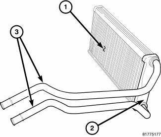
Fig. 226: Heater Core-Description
The heater core (1) for the heating-A/C system is mounted within the HVAC air distribution housing, which is located behind the instrument panel. The heater core is a heat exchanger made of rows of tubes with fins and is positioned within the air distribution housing so that only the selected amount of air entering the housing passes through the heater core before it is distributed through the heating-A/C system ducts and outlets. One end of the heater core is fitted with a tank (2) that includes the fittings for the heater core tubes (3).
The heater core can only be serviced by removing the HVAC housing from the vehicle.
OPERATION
Engine coolant is circulated through the heater hoses to the heater core at all times. As the coolant flows through the heater core, heat is removed from the engine and is transferred to the heater core tubes and fins. Air directed through the heater core picks up the heat from the heater core fins. The blend-air door allows control of the heater output air temperature by regulating the amount of air flowing through the heater core. The blower motor speed controls the volume of air flowing through the HVAC housing.
The heater core cannot be repaired and it must be replaced if inoperative, leaking or damaged.

 Removal, Installation
Removal
WARNING: Refer to the applicable warnings and cautions for this
system before
performing the following operation. Failure to follow the warnings and
cautions may result in po ...
See also:
Reinforcement, bumper, rear
REMOVAL
Fig. 25: Rear Bumper Reinforcement
1. Remove rear fascia. See Removal .
2. Support bumper reinforcement (1) on a suitable lifting device.
3. Mark position of bolts (2) on frame rail ...
TIRE CHAINS
Due to limited clearance, tire chains are not recommended.
CAUTION:
Damage to the vehicle may result if tire chains are
used. ...
EMISSIONS CONTROL SYSTEM MAINTENANCE
The Scheduled Maintenance services listed in bold type,
must be done at the times or mileages specified to ensure
the continued proper functioning of the Emissions Control
System. These, and all ot ...
