Dodge Journey: Removal
2.4L
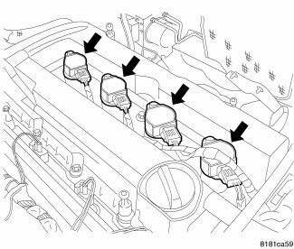
Fig. 11: Identifying Ignition Coil Electrical Connectors
NOTE: Prior to removing coil, spray compressed air around coil top to make sure no dirt drops into the spark plug tube.
The electronic ignition coil attaches directly to the valve cover.
1. Disconnect and isolate the negative battery cable.
2. Remove engine cover.
3. Disconnect electrical connector from ignition coil.
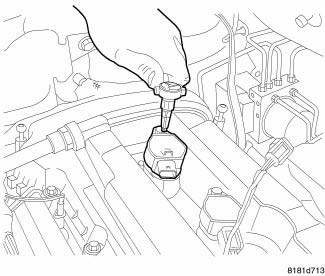
Fig. 12: Removing/Installing Ignition Coil Mounting Bolts
4. Remove ignition coil mounting bolts.
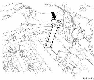
Fig. 13: Removing/Installing Ignition Coil
5. Twist the ignition coil then pull straight up.
2.7L
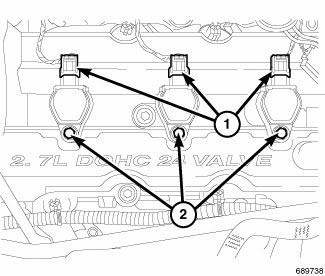
Fig. 14: Removing/Installing Electrical Connectors And Mounting Bolts At
Ignition Coil
NOTE: Always remove the ignition coil assembly by turning the assembly 1/2 turn and pulling up in a steady motion.
1. Disconnect the negative battery cable.
2. Remove the upper intake manifold.
3. Disconnect electrical connector (1) from ignition coil.
4. Remove mounting bolt (2) from ignition coil.
CAUTION: Prior to removing the ignition coils, spray compressed air around the coils and spark plugs. If dirt and debris enter the engine, this may cause internal engine damage.
5. Remove the ignition coils.
3.5L
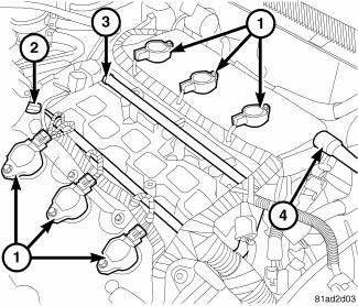
Fig. 15: Ignition Coils And Fuel Rail
1. Remove engine cover.
2. Disconnect and isolate the negative battery cable.
3. Remove the upper intake manifold.
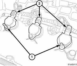
Fig. 16: Ignition Coils
4. Unlock and disconnect electrical connector (2) from ignition coils.
5. Remove mounting bolts and engine cover studs (1).
CAUTION: Prior to removing the ignition coils, spray compressed air around the coils and spark plugs. If dirt and debris enter the engine, this may cause internal engine damage.
6. Twist, lift and remove ignition coil from engine.
 Coil, ignition
...
 Installation
2.4L
Fig. 17: Removing/Installing Ignition Coil
1. Install ignition coil onto spark plug.
Fig. 18: Removing/Installing Ignition Coil Mounting Bolts
2. Install ignition coil mounting bolt, tigh ...
See also:
Cleaning, inspection
CLEANING
To ensure engine gasket sealing, proper surface preparation must be
performed, especially with the use of
aluminum engine components and multi-layer steel cylinder head gaskets.
NOTE: ...
Operation
Following are paragraphs that briefly describe the operation of each of the
major exterior lighting systems. The
lamps and the hard wired circuits between components related to the exterior
light ...
INSTRUMENT CLUSTER
INSTRUMENT CLUSTER ...
