Dodge Journey: Removal
2.7L ENGINE
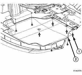
Fig. 22: Belly Pan
- - BELLY PAN
- - EXHAUST EXTENSION PIPE
1. Remove the belly pan (2).
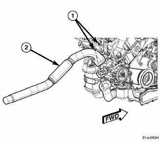
Fig. 23: 2.7L Extension Pipe
2. Remove the fasteners (1), and remove the exhaust extension pipe (2) from the cross under pipe.
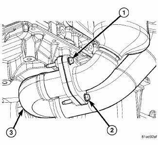
Fig. 24: Cross Under Pipe Fasteners
3. Remove the rear maniverter-to-cross under pipe fasteners (1) and (2).
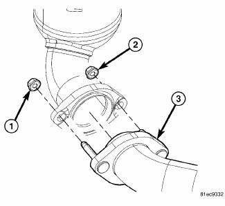
Fig. 25: Maniverter To Cross Under Fasteners
4. Remove the front maniverter-to-cross under fasteners (1) and (2), and remove the cross under pipe (3).
3.5L ENGINE

Fig. 26: Belly Pan
1. Raise vehicle on hoist.
2. Remove the fasteners (1) and remove the belly pan (2).
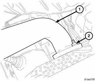
Fig. 27: Exhaust System Pipe
- - EXHAUST PIPE
- - NUTS
3. Disconnect exhaust system pipe (1) from cross under pipe.
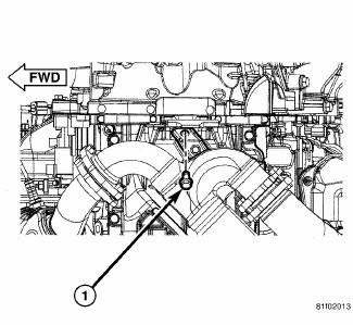
Fig. 28: Cross Under To Bracket
4. Remove cross-under pipe bracket to cross under pipe bolt (1).
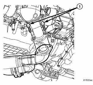
Fig. 29: Left Maniverter To Cross Under
5. Remove cross under to front maniverter bolts and nuts (1).
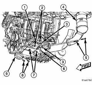
Fig. 30: Cross Under Pipe - 3.5L
- - BRACKET
- - BRACKET MOUNTING BOLTS
- - CROSS UNDER PIPE TO REAR MANIVERTER NUTS
- - REAR MANIVERTER
- - REAR MANIVERTER TO CROSS UNDER BOLTS
- - CROSS UNDER PIP TO BRACKET BOLTS
- - CROSS UNDER PIPE TO FRONT MANIVERTER NUTS
- - CROSS UNDER PIPE TO FRONT MANIVERTER BOLTS
- - FRONT MANIVERTER
6. Remove cross under to rear maniverter bolts (5) and nuts (3).
7. Remove cross under pipe.
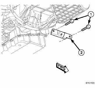
Fig. 31: Cross Under Bracket Transmission Bracket
8. If necessary, remove cross under transmission bracket (2).

 Installation
2.7L ENGINE
Fig. 32: Maniverter To Cross Under Fasteners
1. Install the cross under pipe (3). and the front maniverter-to-cross under
fasteners (1) and (2). Tighten to
27 Nm (20 ft. lb.).
Fi ...
See also:
Flow check
To determine whether coolant is flowing through the cooling system, use one
of the following procedures:
PREFERRED METHOD
WARNING: Do not remove the cooling system pressure cap or any hose ...
Solenoid, evaporative emissions purge
Operation
During the cold start warm-up period and the hot start time delay, the PCM
does not energize the solenoid.
When de-energized, no vapors are purged.
The proportional purge solenoid o ...
Description
The instrument cluster contains the necessary hardware and software to serve
as the vehicle electronic body
control module and is commonly referred to as the Cab Compartment Node (CCN).
The CCN u ...
