Dodge Journey: Pump, air
Description
The air injection pump is located on the left side of the engine compartment. The pump is operated by an internal electrical motor and is mounted to a bracket by rubber isolators. An inlet and outlet air hoses are attached to the air pump. A heat shield is attached at the air pump mounting bracket to ensure that the air pump is not damaged by heat coming off the exhaust system.
Operation
The electric air pump only functions during cold starts. The PCM will not command the electric air pump to run if the engine coolant temperature is 10º Celsius (18º Fahrenheit) above ambient temperature or if the engine coolant temperature is above 37º Celsius (98.6º Fahrenheit). The air pump will not run more than 20 seconds during this cold start condition. The air inlet tube to the electric air pump is equipped with a mass air flow (MAF) sensor. This MAF sensor monitors air flow to the exhaust system and is used to diagnose the system by making sure the correct amount of air, not too much or too little, reaches the exhaust system. Each component of the secondary air system is diagnosed assuming the other part is functioning correctly. The diagnostic tool can command the air pump ON with the key ON and engine OFF (KOEO).
Removal
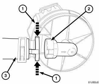
Fig. 2: AIR INLET TUBE AT AIR PUMP
1. Disconnect and isolate negative battery.
2. Remove engine cover.
3. Remove air inlet tube (3) by pushing the ends (1) together while pulling the air inlet tube (3) away from air pump housing connection (2).
4. Remove air outlet tube by pushing the coupling ends together while pulling the air outlet tube away from the air pump.
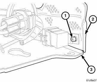
Fig. 3: RELAY
5. Remove bolt (1) from heat shield (2) and air pump bracket (3).

Fig. 4: HEAT SHIELD
6. Remove heat shield bolt (1) and heat shield (3) from air pump bracket (2).
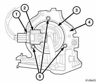
Fig. 5: PUMP TO BRACKET
7. Disconnect electrical harness connector (1) from the air pump electrical connector (2).
8. Remove air pump and bracket assembly from vehicle.
9. Remove air pump mounting nuts (5) from bracket (4).
10. Remove air pump (3) from bracket (4).
Installation

Fig. 6: PUMP TO BRACKET
1. Install air pump (3) to bracket (4).
2. Install air pump mounting nuts (5) to bracket (4). Tighten the nuts to 8 N.m (71 in. lbs.).
3. Position air pump and bracket assembly in vehicle.
4. Connect electrical harness connector (1) to the air pump electrical connector (2).
Fig. 7: HEAT SHIELD
5. Install heat shield (3) and bolt (1) to air pump bracket (2). Tighten the bolt to 8 N.m (71 in. lbs.).

Fig. 8: RELAY
6. Install relay, heat shield (2) and bolt (1) to air pump bracket (3). Tighten the bolt to 8 N.m (71 in. lbs.).

Fig. 9: AIR INLET TUBE AT AIR PUMP
NOTE: The quick connect fitting on the air inlet tube is slotted to fit the air pump housing fitting. Line the slot up when making the connection.
7. Install air inlet tube (3) to air pump housing connection (2). A click noise will indicate a good connection.
8. Install air outlet tube to air pump housing. A click noise will indicate a good connection.
9. Connect the negative battery cable, tighten the nut to 5 N.m (45 in. lbs.).
10. Install engine cover.
 Air injection
...
 Sensor, mass air flow (MAF)
Removal
Fig. 10: MASS AIR FLOW SENSOR
1. Disconnect air flow sensor electrical connector (4).
2. Remove constant tension clamps (1), (2) securing the air flow sensor (3).
3. Remove air flow ...
See also:
Removal
NOTE: Before proceeding, review all Warnings and Cautions.
1. Raise and support the vehicle.
Fig. 39: TIRE AND WHEEL MOUNTING
2. Remove the wheel mounting nuts (3), then the tire and wheel a ...
Air cleaner
REMOVAL
Fig. 85: Air Filter Housing Clips
1. Disengage the air filter housing clips (1).
2. Slide the air filter housing cover (2) forward slightly to disengage tabs
from the bottom of the ai ...
Operation
Fig. 427: Identifying Torque Converter Fluid Pressure
Operation
- APPLY PRESSURE
- THE PISTON MOVES SLIGHTLY
FORWARD
- RELEASE PRESSURE
- THE PISTON MOVES SLIGHTLY
REARWARD
The co ...
