Dodge Journey: Removal
2.4L
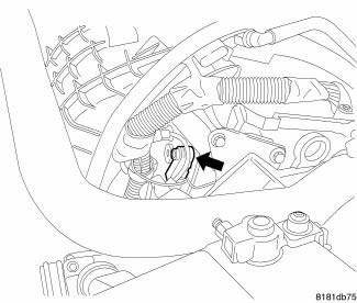
Fig. 45: Locating Knock Sensor
The knock sensor bolts into the side of the cylinder block in front of the starter under the intake manifold.
1. Disconnect and isolate negative battery cable.
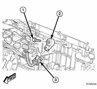
Fig. 46: 2.4L Knock Sensor
2. Disconnect electrical connector (3) from knock sensor (2).
3. Remove bolt (1) and knock sensor (2) from engine block.
2.7L
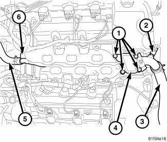
Fig. 47: Water Housing Outlet Tube 2.7L
- - Bolts
- - Coolant Temp Sensor Connector
- - Radiator Upper Hose
- - Water Housing Outlet Tube
- - Heater Hose
- - Retaining Clip
WARNING: Do not remove pressure cap with the system hot and under pressure because serious burns from coolant can occur.
1. Drain cooling system. 2. Disconnect and isolate the negative battery cable.
3. Remove lower intake manifold.
4. Remove radiator upper hose (3) at water housing outlet tube (4).
5. Remove heater hose (5) from water housing outlet tube (4) at rear of engine.
6. Disconnect water housing outlet tube (4) from retaining clip (6) at rear of engine.
7. Disconnect electrical connector (2) from coolant temperature sensor.
8. Remove 4 bolts (1) attaching water housing outlet tube (4) to cylinder heads.
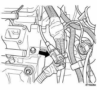
Fig. 48: Knock Sensor Connector
9. Disconnect electrical connector from knock sensor.
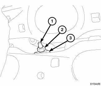
Fig. 49: Knock Sensor 2.7L
- - Stud
- - Nut
- - Knock Sensor
10. Reposition the water housing outlet tube and remove nut (2) from knock sensor mounting stud (1).
11. Remove knock sensor (3) from engine block.
3.5L
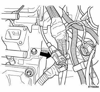
Fig. 50: Knock Sensor Connector
1. Disconnect the negative battery cable.
2. Remove the upper intake manifold.
3. Disconnect the electrical connector.
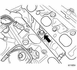
Fig. 51: Knock Sensor Location
4. Remove the knock sensor .
 Sensor, knock
...
 Installation
2.4L
Fig. 52: 2.4L Knock Sensor
CAUTION: Always torque knock sensors to the correct torque
specification. Over or
under tightening effects knock sensor performance. Ensure the electr ...
See also:
Solenoid, evaporative emissions purge
Operation
During the cold start warm-up period and the hot start time delay, the PCM
does not energize the solenoid.
When de-energized, no vapors are purged.
The proportional purge solenoid o ...
Intermediate shaft, gas
REMOVAL
2.4L
1. Remove the right half shaft.
Fig. 44: Intermediate Shaft - 2.4L
2. Remove the three intermediate shaft bolts (1).
3. Remove the intermediate shaft (2).
2.7L
1. Remove the r ...
Diagnosis and Testing
A/C EXPANSION VALVE
WARNING: Refer to the applicable warnings and cautions for this
system before
performing the following operation. Failure to follow the warnings and
cautions may ...
