Dodge Journey: Manifold, exhaust, rear
Removal
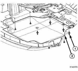
Fig. 305: Belly Pan
- - belly pan fasteners
- - belly pan
1. Remove the belly pan (2).

Fig. 306: Oxygen Sensors
2. Remove the oxygen sensors (2) and (4).

Fig. 307: Exhaust Gas Recirculation Tube
3. Remove the EGR tube (1).

Fig. 308: Rear Maniverter Heat Shield
4. Remove the rear maniverter heat shield (3).
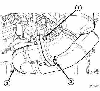
Fig. 309: Exhaust Cross-Under Pipe
5. Remove the rear maniverter-to-crossunder fasteners (1) and (2).
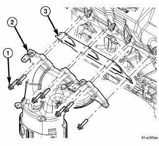
Fig. 310: Rear Maniverter Fasteners
6. Remove the rear maniverter fasteners (1), and the rear maniverter (2).
Inspection
1. Inspect exhaust manifolds for damage or cracks.
2. Check manifold flatness.
3. Inspect the exhaust manifold gasket for obvious discoloration or distortion.
4. Check distortion of the cylinder head mounting surface with a straightedge and thickness gauge.
Installation

Fig. 311: Rear Maniverter Fasteners
1. Install the rear maniverter gasket (3), the rear maniverter (2), and the rear maniverter fasteners (1).
Tighten the rear maniverter fasteners to 23 Nm (17 ft. lb)

Fig. 312: Exhaust Cross-Under Pipe
2. Install the rear maniverter-to-crossunder fasteners (1) and (2). Tighten to 29 Nm (21 ft. lb.).
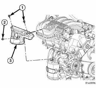
Fig. 313: Rear Maniverter Heat Shield
3. Install the rear maniverter heat shield (3). Tighten fasteners to 12 Nm (106 in. lb.).
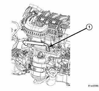
Fig. 314: Exhaust Gas Recirculation Tube
4. Install the EGR tube (1).
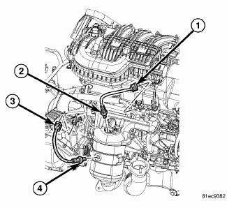
Fig. 315: Oxygen Sensors
5. Install the oxygen sensors (2) and (4). Tighten to 41 Nm (30 ft. lbs.).

Fig. 316: Belly Pan
- - Belly Pan Fasteners
- - Belly Pan
6. Install the belly pan (2).
 Manifold, exhaust, front
Removal
1. Disconnect negative battery cable.
2. Remove the engine cover.
Fig. 295: Oxygen Sensors
3. Disconnect and remove oxygen sensors (2) and (4).
Fig. 296: Upper Maniverter Heat Shiel ...
 Manifold, intake
Diagnosis and Testing
INTAKE MANIFOLD LEAKS
An intake manifold air leak is characterized by lower than normal manifold
vacuum. Also, one or more
cylinders may not be functioning.
WARNING: ...
See also:
Description, Diagnosis and Testing
DESCRIPTION
The inner joints of both half shaft assemblies are tripod joints. The outer
joints of both assemblies are Rzeppa
Joints. The tripod joints are true constant velocity (CV) joint assembl ...
POWER INVERTER — IF EQUIPPED
Your vehicle may be equipped with a 115 Volt AC (150
Watt maximum) power outlet located on the back of the
center console. This outlet can power cellular phones,
electronics and other low power dev ...
Removal
WARNING: Refer to the applicable warnings and cautions for this
system before
performing the following operation. Failure to follow the warnings and
cautions may result in possible se ...
